Keyscan Inc. A Member of the Kaba Group – CA150 Rev. B Installation Guide (07.15)
Locate & Mount the CA150
Locate the area where the CA150 and, if required, the power supply, are going to be mounted. Follow the
mounting procedures on the following page. Keyscan recommends a vertical mount on a solid, smooth surface.
Do not mount the access control unit close to high-voltage equipment. Comply with all local and regional
codes. Record the serial number listed on the control board. The serial number is a required entry in the
Keyscan Client software. The CA150 includes a mounting template for drilling holes to mount the unit.
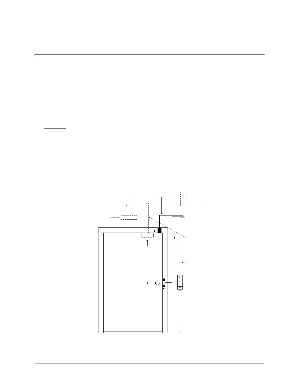
The following illustration shows a typical mounting location for the CA150 which generally is in proximity to the
door it is controlling. However circumstances may require mounting the unit farther from the door than
depicted.
Important
When locating a mounting position, bear in mind if the CA150 has access to the network and/or power
depending on how the unit is being configured – network (TCP/IP), RS-232 (direct serial), PoE or a local
+12V DC power supply.
The CA150 is a standalone single door control unit; it does not support CIM, CB-485 or CPB-10-2
connections to other control units. The CA150 does not support global functions.
Figure 1 – Typical Door Layout
CA150
Control Unit
Reader
Request
to exit
PIR
36" to 48"
(91.4 to 121.9 cm)
Door contact
6 conductors shielded
22 or 18 AWG
2 pairs
22 AWG
1 pair 18 AWG
Mag Lock
Door
Strike
1 pair
22 AWG
KEYSCAN
Power
PoE
or
+12VDC
KI-00321E-07-11