Keyscan Inc. A Member of the Kaba Group – CA150 Rev. B Installation Guide (07.15)
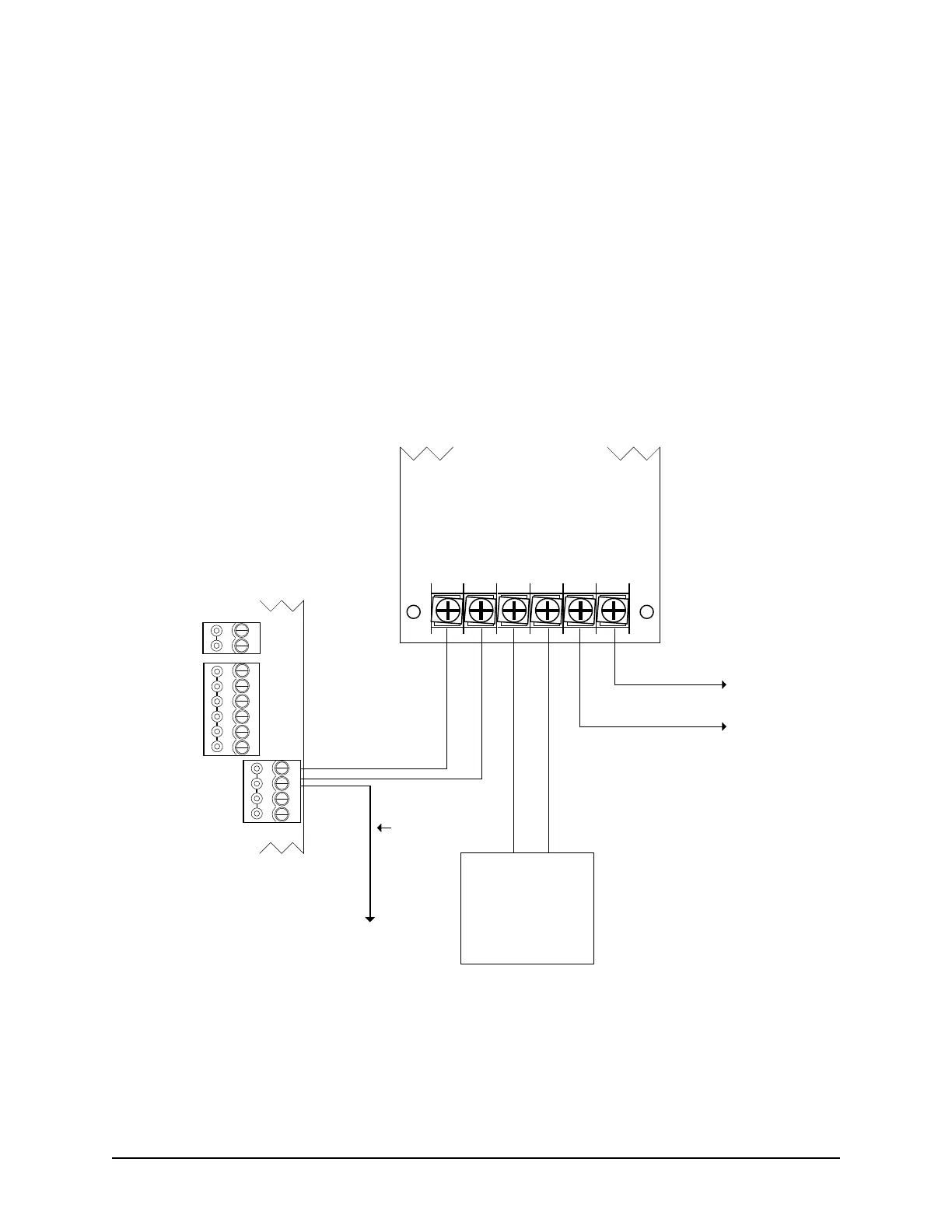
DC Power Supply +12V DC
Ensure the right cover on the CA150 control board has been removed.
Connect the +12V DC power supply to the POWER IN terminals (TB6) on the CA150.
Upon applying power, the CA150 begins booting-up. The system status LED illuminates in amber and
the on-board piezo emits a beep.
Using a voltmeter, check the following terminals on the CA150 for +12V DC:
Reader 1 – PWR RED
Reader 2 – PWR RED
POWER OUT + (TB6)
DOOR output N/C or N/O (if set on POWERED)
AUX output N/C or N/O (if set on POWERED)
Figure 36 – Power Supply Wiring
POWER
INOUT
-
+
-
+
DOOR
AUX.
N/C
(+)
COM
(-)
N/O
(+)
N/C
(+)
COM
(-)
N/O
(+)
RS-485
A
B
(+ 12 VDC)
CA150B
Control Board
Cut View
+ DC - + BAT - AC AC
12V Backup Battery
4 Ah minimum
+ -
Red (+)
Black (-)
Red
(+)
Black
(-)
Cut View
Power Supply/Charger
Black
White
set power supply
to +12V DC
to AC transformer
to ACU
ground
lug
#18 AWG
Green*
* Required for either PoE or
ungrounded power supply
KI-00355E-10-13
CA150B
Maximum current draw 200 mA