Keyscan Inc. A Member of the Kaba Group – CA150 Rev. B Installation Guide (07.15)
J1 - Restore Default Settings/Clear Memory
Jumper J1 is used to restore the control board’s factory default settings. You must restore the factory default
settings whenever one or more of the following procedures are undertaken on the CA150 control board:
when a control board has been newly installed
when the CA150 has had a flash memory upgrade
when system software mode DIP switches S2.9 / S2.10 have been changed
when temporary card countdown DIP switch S1.7 has been changed
Procedure
To restore the factory default settings, ensure the control board has power, enable DIP switch S1.9, short
J1 momentarily, and then disable DIP switch S1.9.
After placing the jumper on J1, the system status LED begins flashing red and the control board’s piezo
emits a cycle of 2 short beeps followed by a pause. This occurs for approximately 2 minutes while the
factory default settings are loaded and the database information is erased from the on-board memory. Do
not make any changes to the control board, such as altering jumpers or powering down the board, while
the factory defaults are being restored or you will have to repeat the procedure. After the system status
LED has stopped flashing, the factory default settings have been restored and the Keyscan database has
been cleared from the on-board memory. After you have restored the factory defaults, perform an upload
from a PC with a Keyscan Client software module so the Keyscan database is transferred to the control
board’s on-board memory.
If this is a new installation, enter the site information in the Keyscan Client software and then upload the
Keyscan database information to the control board(s). Until you perform an upload from a Keyscan Client, the
access control unit(s) will not function.
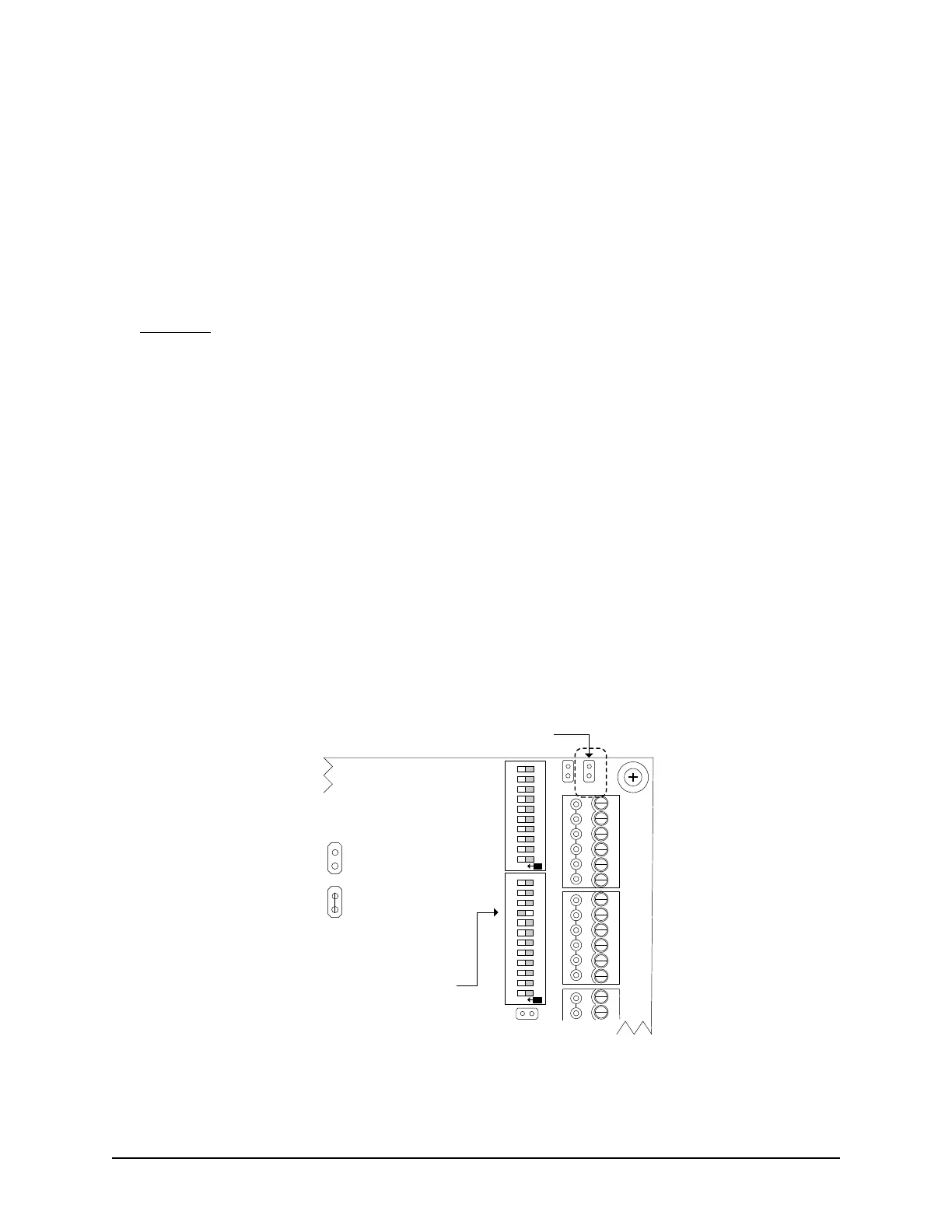
Figure 26 – Restore Default Settings (Clear Memory) J1 Location
AUX2
-
+
READER 1
READER 2
C1
(BEEP)
LED
D1
WHITE
D0
GREEN
PWR
RED
GND
BLK
C1
(BEEP)
LED
D1
WHITE
D0
GREEN
PWR
RED
GND
BLK
J6
J4
J1
RDR
RST.
CLR
MEM.
SYS.
RST.
Location of Clear Memory Jumper J1
Cut view with right
cover removed.
KI-00349E-02-14
RDR/SUPV. CONFIG.SYSTEM CONFIG.
ON
6
7
8
9
10
2
3
4
5
1
6
7
8
9
10
2
3
4
5
1
11 12
ON
S1
S2
Jumper Off
Off = 0
Jumper On
On = 1
Jumper Settings
Enable Clear Memory
DIP Switch S1.9 = ON