Keyscan Inc. A Member of the Kaba Group – CA150 Rev. B Installation Guide (07.15)
KI-00323E-07-14
CARD
BITS
10s
1s
SYSTEM
STATUS
COMMUNICATION
STATUS
TD 1
RD 1
TD 2
RD 2
SYSTEM
INPUTS/
RS-485
(TB7)
SERVER
RS-232 (TB5)
ETHERNET
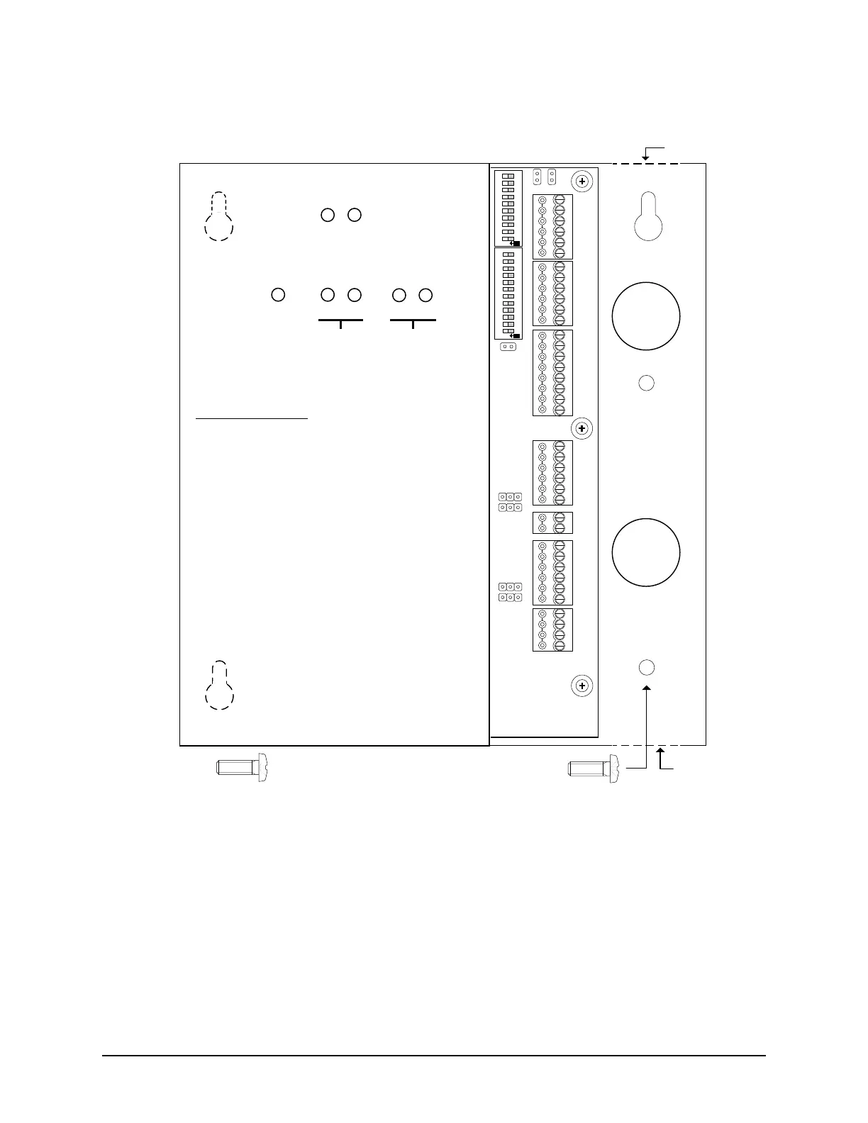
Front View of CA150 with the right cover removed
Keyway
Cutout
Keyway
Cutout
Keyway
Cutout
CA150B
Left Cover
(Do not remove.)
Mounting Guidelines
- Unfasten the 2 knurled screw heads to remove the right cover
- Use the enclosed mounting template and drill 4 holes where
indicated
- Fasten the top 2 screws and the lower left screw until there is a
gap of approximately 1/32” between each of the screw heads
and the mounting surface
- Mount the CA150 so that the 3 keyway cutouts at the back of
the enclosure are over the screw heads
- Slide the enclosure down until the 3 screws are seated at the
top of the keyway cutouts
- If necessary, remove unit and adjust the screws to have the
unit fit tight between the screw heads and the mounting
surface, then slide the enclosure down until the 3 screws are
seated at the top of the keyway cutouts
- Fasten and tighten the 4
th
screw in the lower right hole
x3 for Keyway
Cutouts
x1
Knock-outs - 7/8"
(2.2225 cm)
Knock-out
Knock-out
Knock-out
Knock-out
Rev. B