EasyManuals Logo

Keyscan CA150 User Manual

Keyscan CA150
113 pages
To Next Page IconTo Next Page
To Previous Page IconTo Previous Page
Page #63 background imageLoading...
Page #63 background image
Keyscan Inc. A Member of the Kaba Group CA150 Rev. B Installation Guide (07.15)
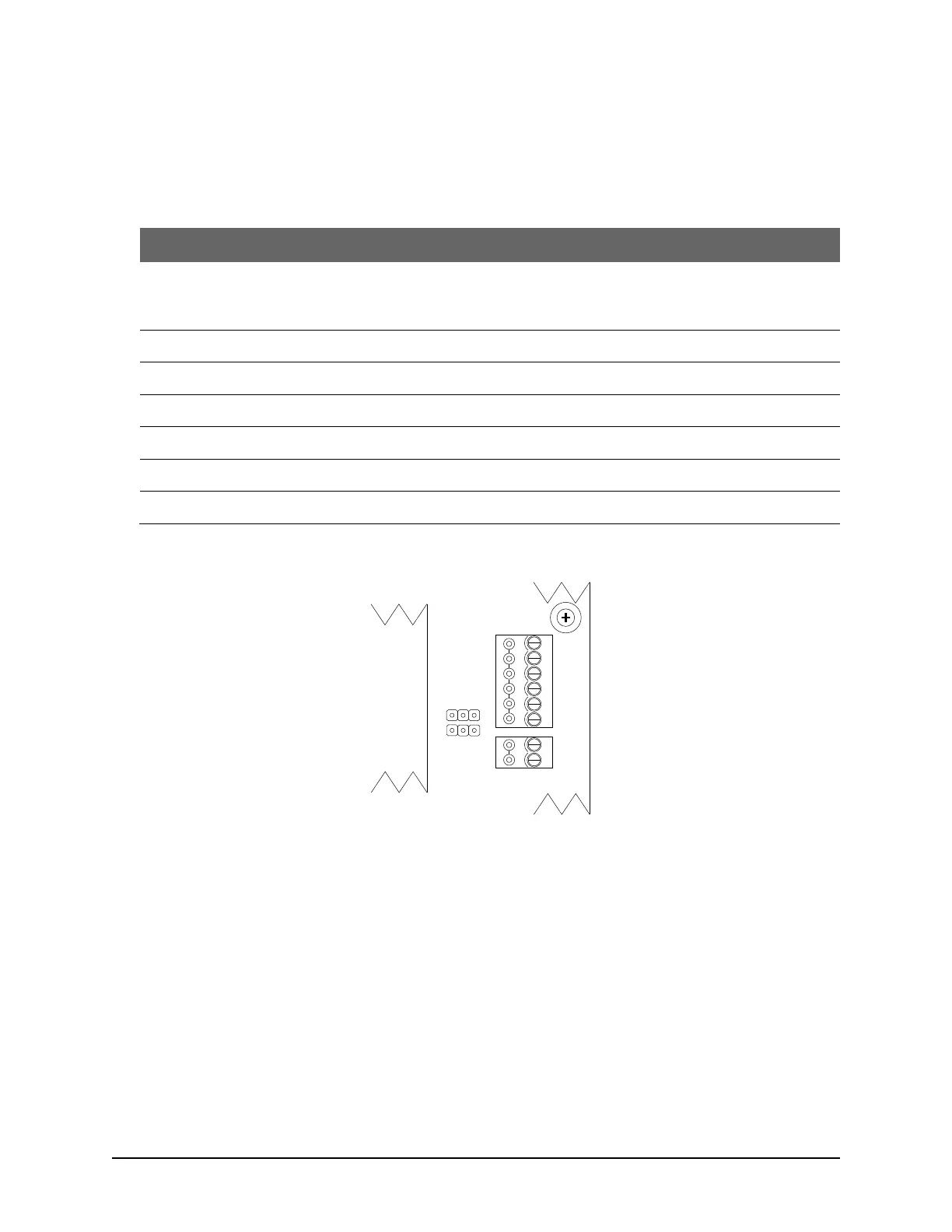
63
Test Points Communication Terminals
The following table outlines the correct voltages for the test points on the RS-232 communication terminal.
Table 10 Communication Voltage Test Points
Communication Test Point
Voltage
Instructions/Notes
Control Board Communication
Terminal
RS-232 connected to ACU
Connect Voltmeter COM to GND on ACU communication
terminal block or green on data cable.
GND
TD
(-) 9 VDC
TD is an ACU generated voltage
RD
(-) 10 VDC
RD is a PC generated voltage
DCD
Used for modems only
DTR
n/a
CTS
n/a
Figure 38 Control Board Communication Test Points
RS-485
A
B
RS-232
CTS
DTR
DCD
RD
TD
GND
J10
J11
Left Cover
KI-00357E-05-12

Table of Contents

Questions and Answers:

Question and Answer IconNeed help?

Do you have a question about the Keyscan CA150 and is the answer not in the manual?

Keyscan CA150 Specifications

General IconGeneral
BrandKeyscan
ModelCA150
CategoryControl Unit
LanguageEnglish

Related product manuals