Keyscan Inc. A Member of the Kaba Group – CA150 Rev. B Installation Guide (07.15)
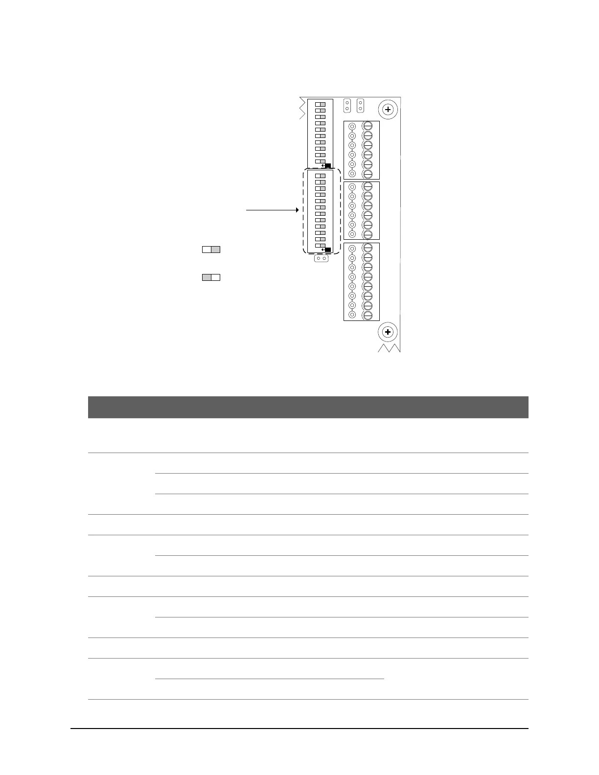
Figure 21 – System Configuration DIP Switches S1.1 – S1.12
Table 3 – System Configuration DIP Switch S1 Settings
Serial Communication – standard polling
Also see S1.10 & S1.11 in the table.
Network Communication – standard polling
Reverse Network Communication
Requires a license from Keyscan.
Alternate Panel Serial # Selection
Factory-assigned serial #
Only set DIP switch for alternate serial
number if prompted in the Client
software when adding a panel.
Adds 1000 to factory-assigned serial #
DOOR
RTE AUX1 AUX2
-
+
-
+
-
+
-
+
READER 1
READER 2
C1
(BEEP)
LED
D1
WHITE
D0
GREEN
PWR
RED
GND
BLK
C1
(BEEP)
LED
D1
WHITE
D0
GREEN
PWR
RED
GND
BLK
J6
J4
J1
RDR
RST.
CLR
MEM.
SYS.
RST.
Location of System
Configuration DIP Switches
S1.1 to S1.12
Cut view with right
cover removed.
KI-00341E-02-14
RDR/SUPV. CONFIG.SYSTEM CONFIG.
ON
6
7
8
9
10
2
3
4
5
1
6
7
8
9
10
2
3
4
5
1
11 12
ON
S1
S2
Switch Off
Off = 0
Switch On
On = 1
Switch Settings