Keyscan Inc. A Member of the Kaba Group – CA150 Rev. B Installation Guide (07.15)
Set System Configuration DIP Switches
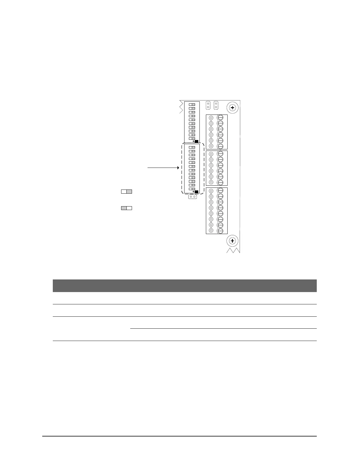
Set DIP switch S1.1 for reverse network communication and DIP switch S1.2 for the bit rate as outlined in the
table below.
Figure 65 – Location of S1.1 / S1.2 DIP Switches
Table 16 - System Configuration DIP Switches S1.1 & S1.2 – Reverse Network Settings
Set IP Address on Access Control Board
This procedure requires Keyscan’s Hyper Terminal application on a PC or laptop that can connect with the
access control unit. Keyscan’s Hyper Terminal application is accessible from the NETCOM Program Utility on
the Keyscan Divers & Utilities CD.
This procedure also requires a serial data cable.
1. Ensure that the access control board has power.
DOOR
RTE AUX1 AUX2
-
+
-
+
-
+
-
+
READER 1
READER 2
C1
(BEEP)
LED
D1
WHITE
D0
GREEN
PWR
RED
GND
BLK
C1
(BEEP)
LED
D1
WHITE
D0
GREEN
PWR
RED
GND
BLK
J6
J4
J1
RDR
RST.
CLR
MEM.
SYS.
RST.
Location of System
Configuration DIP Switches
S1.1 to S1.12
Cut view with right
cover removed.
KI-00341E-02-14
RDR/SUPV. CONFIG.SYSTEM CONFIG.
ON
6
7
8
9
10
2
3
4
5
1
6
7
8
9
10
2
3
4
5
1
11 12
ON
S1
S2
Switch Off
Off = 0
Switch On
On = 1
Switch Settings