Keyscan Inc. A Member of the Kaba Group – CA150 Rev. B Installation Guide (07.15)
Readers
Never mount readers close to high-voltage equipment. For convenient entry, the reader should be mounted at
a convenient height on the latch side of the door.
When mounting proximity readers for monitoring in and out activity at the same door, space the readers at a
distance greater than the combined radio signal read ranges. As an example, if the read range is 4 inches,
mount the two readers at a distance greater than 8 inches from each other.
For mounting readers to a metal surface, consult with the manufacturer's documentation.
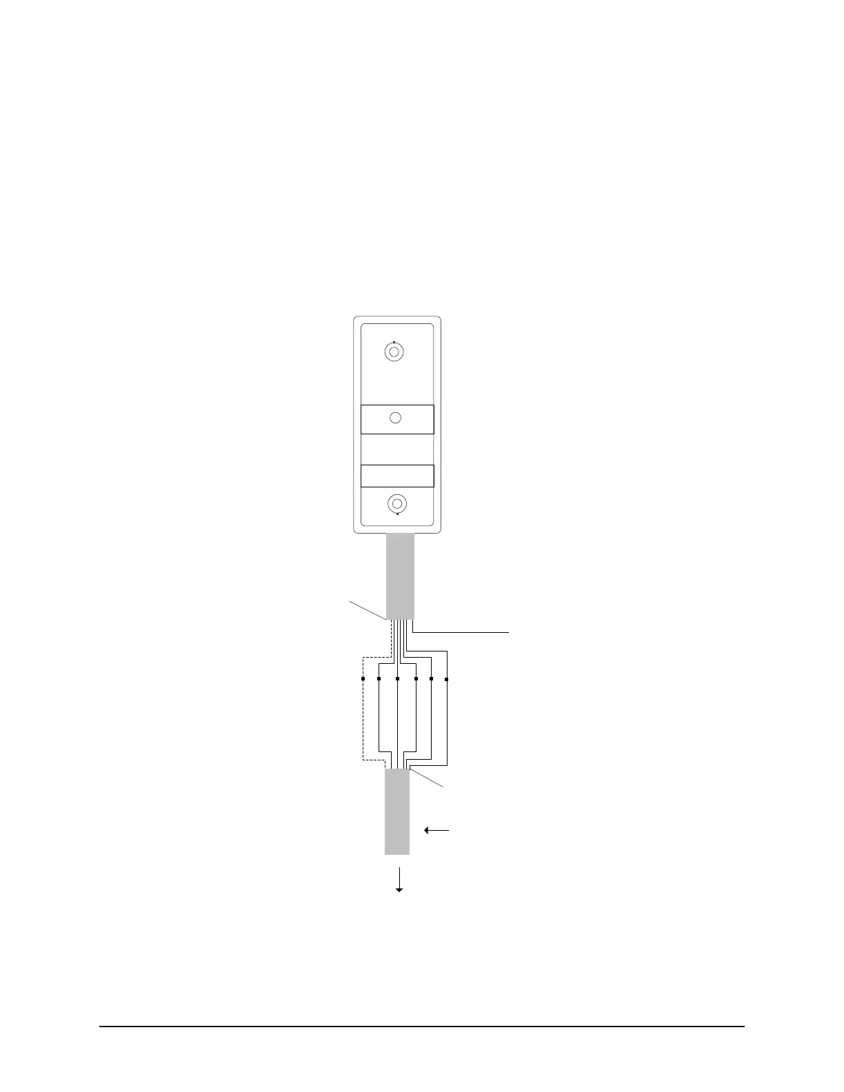
Figure 6 – Typical Door Reader Connection
Proximity Reader
(Refer to specific
Keyscan, HID & Indala
readers for wiring
connections.)
To reader terminal on
ACU
LED (Brown)
D1 (White)
D0 (Green)
PWR (Red)
GND (Black)
Shield not connected.
Isolate with electrical tape.
6 conductors shielded 18 or 22 AWG
Maximum 500 ft (152.4 m)
Blue used for pre-
alert otherwise
isolate and tape
back.
Orange not
used. Isolate
and tape back.
KEYSCAN
Pre-alert (Blue)
Shield not connected.
Isolate with electrical tape.
KI-00123E-07-11