Keyscan Inc. A Member of the Kaba Group – CA150 Rev. B Installation Guide (07.15)
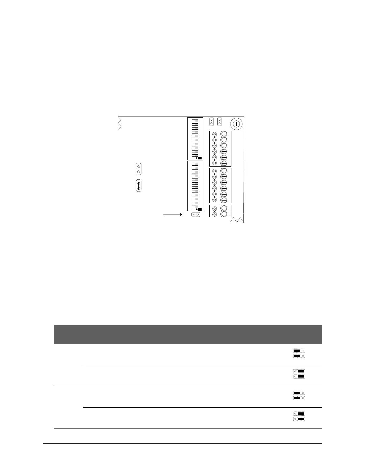
J6 - System Reset
Excluding the changes outlined under Restore Default Settings on the preceding page, whenever you have
changed the DIP switches or altered jumpers on the CA150 control board while it is powered, perform a
system reset by momentarily placing a jumper on J6.
Figure 27 – Location of System Reset Jumper J6
Door & AUX Outputs – Powered/Unpowered
The door output relay and the AUX output relay are each fused at 500 mA. Each output has a set of jumpers
which configures the output to source power from the CA150 or configures the output as a dry contact. When
the output is configured as a dry contact, the connected device requires an independent power source.
The AUX output may also be configured as an accessibility output. See page 51.
Table 7 - Powered/Unpowered Jumper Settings for Door & AUX Outputs
AUX2
-
+
READER 1
READER 2
C1
(BEEP)
LED
D1
WHITE
D0
GREEN
PWR
RED
GND
BLK
C1
(BEEP)
LED
D1
WHITE
D0
GREEN
PWR
RED
GND
BLK
J6
J4
J1
RDR
RST.
CLR
MEM.
SYS.
RST.
Location of System
Reset Jumper J6
Cut view with right
cover removed.
RDR/SUPV. CONFIG.SYSTEM CONFIG.
ON
6
7
8
9
10
2
3
4
5
1
6
7
8
9
10
2
3
4
5
1
11 12
ON
S1
S2
Jumper Off
Off = 0
Jumper On
On = 1
Jumper Settings
KI-00517E-02-14