Keysight B1505A User’s Guide, Edition 12 3-17
Accessories
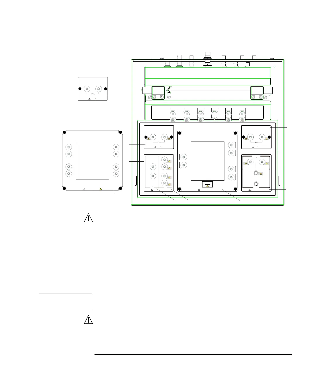
1. Module Selector Output (N1259A-300)
See Figure 3-2 and Table 3-2 for the status indicator and the connection path.
a. Low Force and Sense output terminals
Force and Sense must be connected together at the low terminal of a DUT.
b. High Force, Sense, and Guard output terminals
Force and Sense must be connected together at the high terminal of a DUT.
And Guard must be opened. You may extend it as close as possible to the
DUT terminal for reducing the leakage current of the extension cable.
NOTE Module selector may emit a noise sound during operation. However it is not
abnormal status.
2. Resistor box
For reducing damage of DUT or preventing SMU from oscillation. The
following resistors are available by the options.
2
1
2
3
4
b
a
High Voltage Bias– Tee
Guard
Module Selector Output
Force
Sense
Guard
Sense
Force
1 MΩ
21
100 kΩ
HighLow
21
±3 kV Max±40 V Max
N1259A
Opt 022
±3 kV Max
Max: 6.4 W
±3 kV Max
Max: 9 W
N1259A
Opt 021
N1259A
Opt 010
Force
Sense
Force
Sense
Force
Sense
1
2
3
123
±3 kV Max
Inline Package Socket (3 Pin)
Kelvin Connection
MF CMU
DC Bias Input
±3 kV Max
High
Low
Force
±3 kV Max
±25 V Max
Guard
5
2
51
2
3
4
6
7
8
N1259A
Opt 011
±3 kV Max
Universal Socket Module
1 kΩ
21
±2 00 V Max
Max: 1 W
N1259A
Opt 030