3-48 Keysight B1505A User’s Guide, Edition 12
Accessories
WARNING Make enough space between the socket/DUT terminal and the shield/chassis,
for example, about 1 mm for maximum 200 V output and 6 mm for 3000 V, to
prevent discharge and any accident.
Laissez suffisamment d'espace entre la prise/la borne MST et la protection/le
châssis. Par exemple, environ 1 mm pour une sortie de 200 V au maximum et 6
mm pour 3 000 V afin d'éviter toute décharge et tout accident.
7. Reattach the cover.
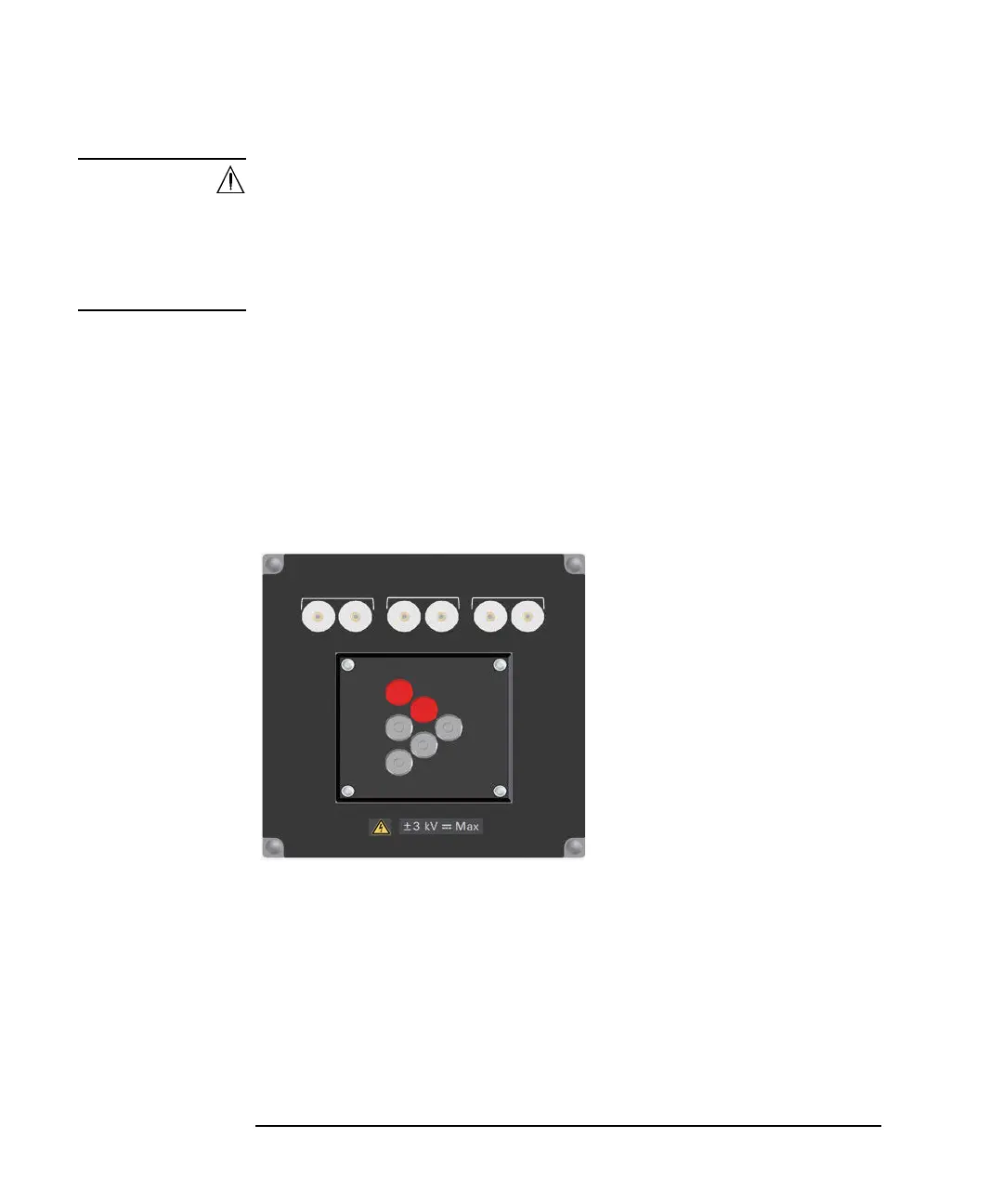
• Curve Tracer Test Adapter Socket Module (N1265A-013)
This module provides a socket available for connecting a test adapter designed
for connecting to Tektronix 370B/371B curve tracers. Socket module internal
connection is shown in Figure 3-14.
To use this module, see the following simple instruction.
Figure 3-14 Curve Tracer Test Adapter Socket Module
1. Attach the socket module to the test fixture.
2. Connect your test adapter to the socket.
3. Connect wires between the socket module terminals and the fixture output
terminals. Then use the following wire.
• N1254A-522 wire (yellow) for Selector Output High/Low Force
• N1254A-508 or 509 wire for Selector Output High/Low Sense, Gate,
SMU, or chassis
Collector / Drain
Emier / Source Base / Gate
N1265A Opt 013
Force Sense
Force Sense
Force Sense
Curve Tracer Test Adapter Socket
1
2
5
6
4
3
Internal connection
1: Collector/Drain Force
2: Collector/Drain Sense
3: Emitter/Source Force
4: Emitter/Source Sense
5: Base/Gate Force
6: Base/Gate Sense
Maximum voltage: 3000 V
Maximum current:
A-Force: 500 A pulse, 39 A dc
A-Sense: 40 A pulse, 2 A dc
B-Force: 500 A pulse, 39 A dc
B-Sense: 40 A pulse, 2 A dc
C-Force: 40 A pulse, 2 A dc
C-Sense: 40 A pulse, 2 A dc
A
BC