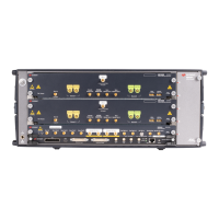
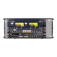
Only relevant parameters and edition fields are shown in the GUI at any time depending
on the selected generation mode (Direct/Up-converter) and modulation scheme.
Waveform Destination Section
Generate Baseband Data
It is always seleced while in up-converter modes. If checked while in direct mode, it
will assign the I (In-phase) component to Channel 1 and the Q (Quadrature)
component to Channel 2.
Apply Offset Freq.
This checkbox is only active for up-converter modes and it applies a frequency shift
to the signal according to the ‘Offset Freq.’ edition field. Frequency shift, unlike
carrier frequency, may be positive or negative.
Spectrum Reversed
This checkbox must be selected for generation of signals in the second Nyquist
band (FS/2 – FS). Its effect is the reversion of the fundamental signal (in the 1st
Nyquist Band) in the frequency domain. It also reverses the effect of any correction
so correction factors obtained for the second Nyquist band will be applied
appropriately.
 Loading...
