TOS5300 77
Specifications
8
Specifications
TOS5300 TOS5301 TOS5302
Voltmeter Analog Scale 6 kV AC/DC f.s
Accuracy ±5 % f.s
Indication Mean-value response/rms scale
Digital Measurement
range
0.000 kV to 6.500 kV AC/DC
Display
□ . □□□ kV
Accuracy V < 500 V: ±(1.5 % of rdng + 20 V); V ≥ 500 V: ±1.5 % of rdng
Response
3
True rms/ Mean-value response rms display Can be switched
Hold feature After a test is finished, the measured voltage is retained until the PASS or FAIL judgment is cleared.
Ammeter Digital Measurement
range
AC: 0.00 mA to 110 mA AC: 0.00 mA to 110 mA
DC: 0.00 mA to 11 mA
AC: 0.00 mA to 110 mA
Display i = measured current
Accuracy
4
1.00 mA ≤ i: ±(1.5 % of rdng); i < 1.00 mA: ±(1.5 % of rdng + 30 μA)
Response
3
True rms/ Mean-value response rms display Can be switched
Hold feature After a test is finished, the measured current is retained until the PASS judgment is cleared.
Judgment
feature
Judgment method and
judgment operation
• If PASS HOLD is enabled, the PASS signal is generated continuously until the TOS5300 Series receives
a STOP signal.
• The UPPER FAIL and LOWER FAIL signals are generated continuously until the TOS5300 Series
receives a STOP signal.
• The FAIL and PASS buzzer volume levels can be changed.
• For PASS judgments, the length of time that the buzzer sounds for is fixed to 0.2 seconds. Even if PASS
HOLD is enabled, the buzzer turns off after 0.2 seconds.
Upper limit setting AC: 0.01 mA to 110 mA AC: 0.01 mA to 110 mA
DC: 0.01 mA to 11 mA
AC: 0.01 mA to 110 mA
Lower limit setting AC: 0.01 mA to 110 mA / OFF AC: 0.01 mA to 110 mA / OFF
DC: 0.01 mA to 11 mA / OFF
AC: 0.01 mA to 110 mA / OFF
Judgment accuracy
4
1.00 mA ≤ i: ±(1.5 % of set), i < 1.00 mA: ±(1.5 % of set + 30 μA)
Current detection method Calculates the current’s true rms value or mean-value and compares this value with the reference
value
Calibration Calibrated with the rms of a sine wave using a pure resistive load
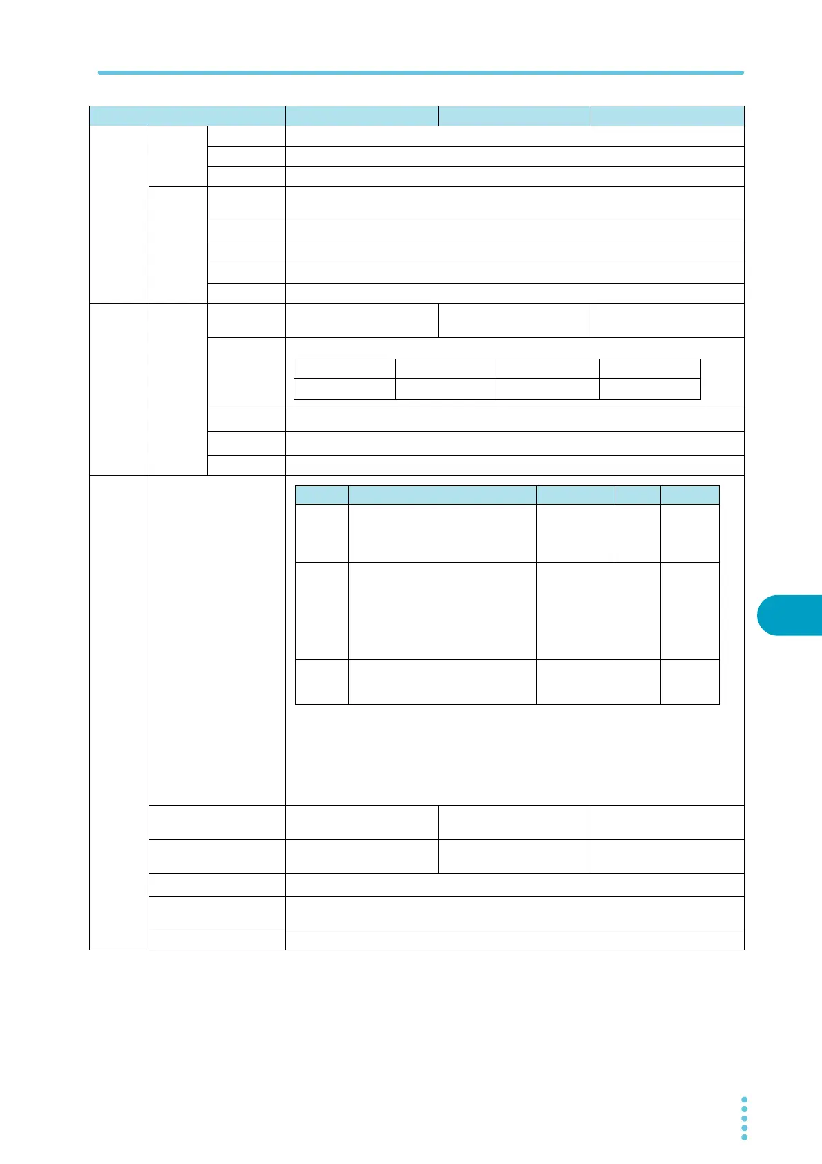
i < 1 mA 1 mA ≤ i < 10 mA 10 mA ≤ i < 100 mA 100 mA ≤ i
□□□ μA
□ . □□□ mA □□ . □□ mA □□□ . □ mA
Judgment Judgment method Display Buzzer SIGNAL I/O
UPPER
FAIL
If a current that is greater than or equal to
the upper limit is detected, the output is
turned off, and an UPPER FAIL judgment
occurs.
FAIL LED lights
OVER is
displayed on
the screen
ON
Generates
a U-FAIL
signal
LOWER
FAIL
If a current that is less than or equal to the
lower limit is detected, the output is
turned off, and a LOWER FAIL judgment
occurs. This judgment is not performed
during voltage rise time (Rise Time) of all
tests and during the voltage fall time (Fall
Time) of AC withstanding voltage tests.
FAIL LED lights
UNDER is
displayed on
the screen
ON
Generates
an L-FAIL
signal
PASS
If the specified time elapses without any
problems, the output is turned off, and a
PASS judgment occurs.
PASS LED lights ON
Generates
a PASS
signal