78 TOS5300
Specifications
TOS5300 TOS5301 TOS5302
Time Voltage rise time 0.1 s to 10.0 s
Resolution 0.1 s
Voltage fall time 0.1 s / OFF (only enabled when a PASS judgment occurs)
Test time 0.1 s to 999 s, can be turned off (TIMER OFF)
Resolution 0.1 s to 99.9 s: 0.1 s. 100 s to 999 s: 1 s.
Accuracy ±(100 ppm + 20 ms)
AC: Excluding Fall Time
DC: Rise Time Add ±50 ms at 1 kV or more, Add ±100 ms at less than 1kV.
1 Regarding the output time limits:
Taking size, weight, and cost into consideration, the heat dissipation capability of the voltage generator that is used for withstanding voltage
tests has been designed to be one half that of the rated output. Use the TOS5300 Series within the following limits. If you use the product in
a manner that exceeds these limits, the output section may overheat, and the internal protection circuits may be activated. If this happens,
stop testing, and wait until the TOS5300 Series returns to its normal temperature.
2 Regarding the test voltage waveform:
Waveform distortions may occur if an DUT whose capacitance is dependent on voltage (for example, an DUT that consists of ceramic
capacitors) is connected as the load. However, if the test voltage is 1.5 kV, the effect of a capacitance of 1000 pF or less can be ignored.
Because the product’s high-voltage power supply uses the PWM switching method, if the test voltage is 500 V or less, the switching and spike
noise proportions are large. The lower the test voltage, the greater the waveform is distorted.
3 For both True rms and Mean-value response, 50 ms or above response time is required to satisfy the measurement accuracy.
4 Regarding ammeter and judgment accuracy:
During AC withstanding voltage tests, current also flows in the stray capacitance of items such as the measurement leads and jigs. This
current that flows in the stray capacitances is added to the current that flows in the DUT, and the sum of these currents is measured. Especially
if you want to perform judgments with high sensitivity and accuracy, it is necessary to consider methods to limit the current that flows in
these stray capacitances, such as by adding upper and lower limits.
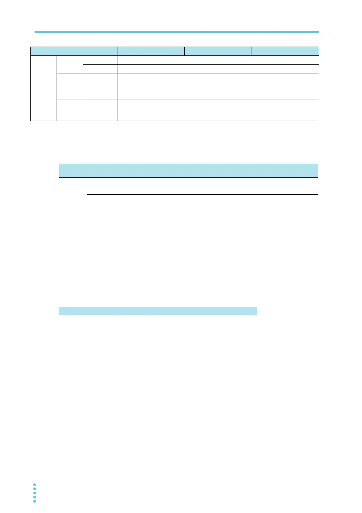
(Output time = voltage rise time + test time + voltage fall time)
Ambient
temperature
Upper limit Pause time Output time
t
≤ 40 °C
AC
50 mA < i ≤ 110 mA
Greater than or equal to the output time 30 min. max.
i
≤ 50 mA
Not necessary Continuous output possible
DC
5 mA < i ≤ 11 mA
Greater than or equal to the output time 1 min. max.
i ≤ 5 mA
Greater than or equal to the wait time
(WAIT TIME)
Continuous output possible
Output voltage 1 kV 2 kV 3 kV 4 kV 5 kV
When using 350 mm long test
leads that are suspended in air
(TYP)
2 μA 4 μA 6 μA 8 μA 10 μA
When using the accessory, high-
voltage test lead TL31-TOS (TYP)
16
μA 32 μA 48 μA 64 μA 80 μA