6
INFORMATION FOR REPLACING THE
FUNCTIONAL UNITS
EN 68
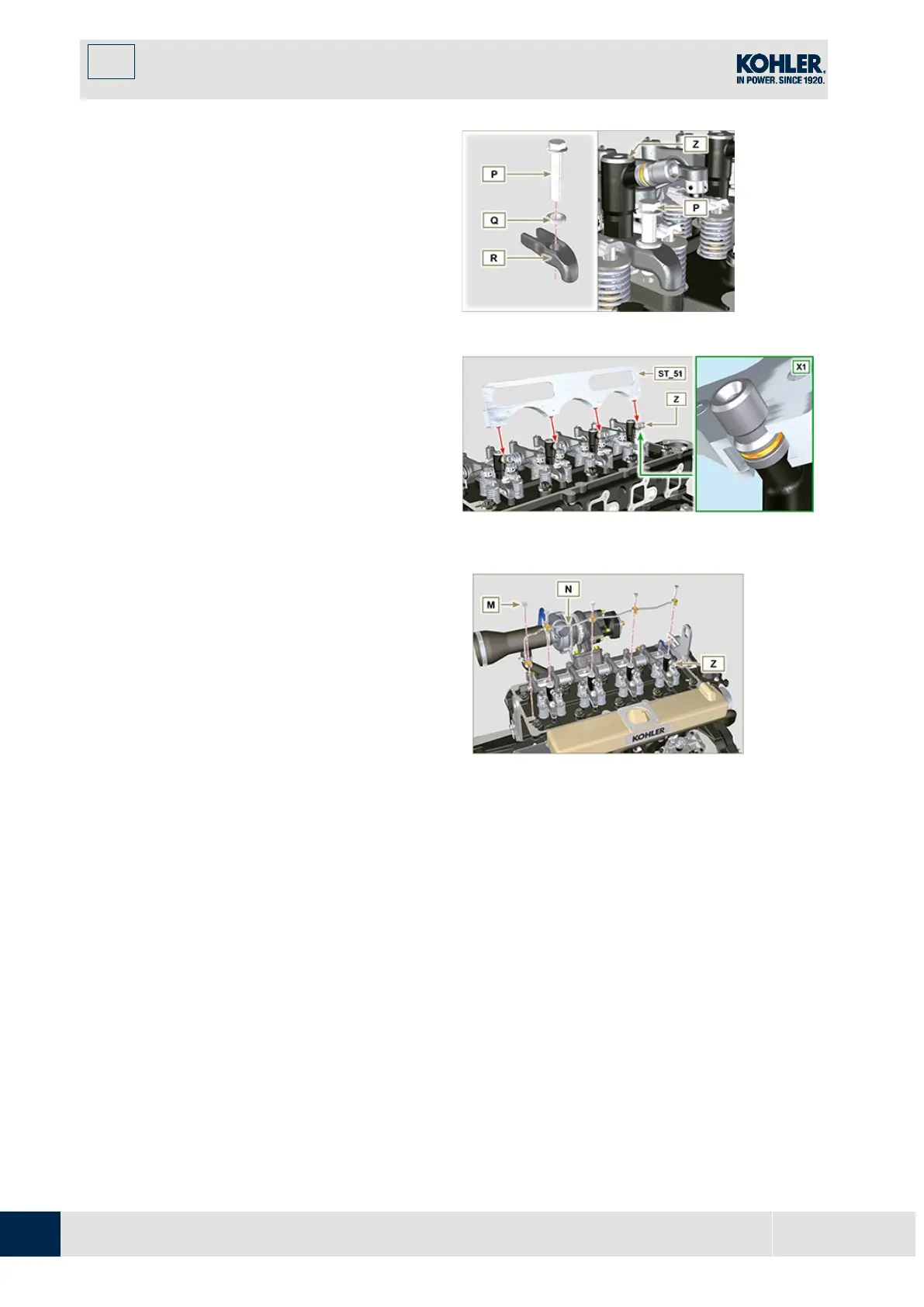
3. Assemble the parts
P, Q, R
and fit the parts so
assembled on the injector
Z
.
Fig 6.22
4. Insert tool
ST_51
on the injectors junctions
Z
(detail
X1
).
5.
Tighten the screw
P
(tightening torque to
20 Nm
)
Fig 6.23
6.1.8 Assembly of the injector return pipes
1.
Position the tube N on the injectors Z, an
d
ti
ghten screws M (tightening torque to 14
Nm).
Fig 6.24

 Loading...


