2MV
2-3-50
YC5
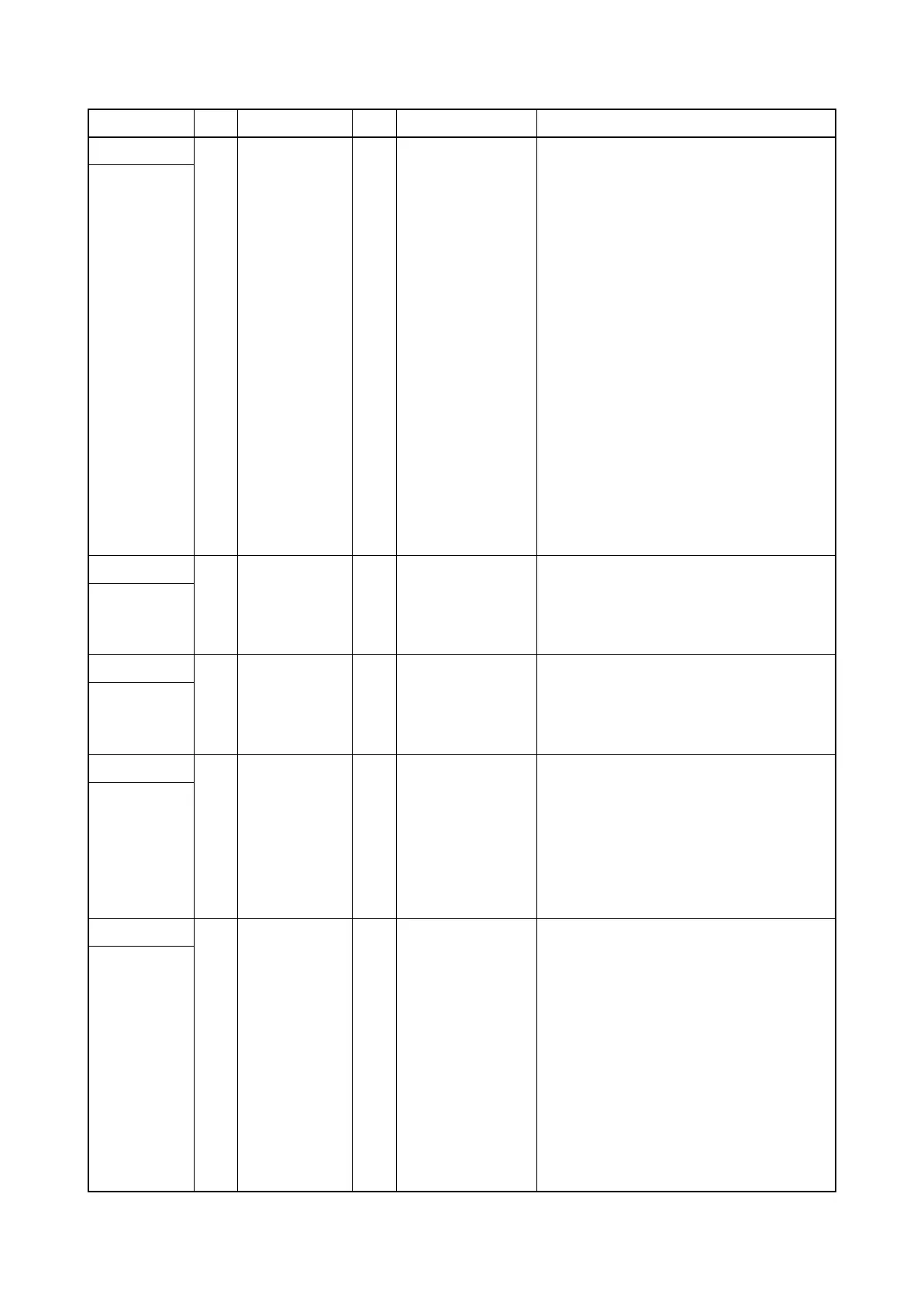
1 ANODE O 3.3 V DC 3.3 V DC power output to DPPFS
DConnected
to DP paper
feed
sensor,DP
registration
sensor,DP
open/close
sensor,DP
switchback
sensor and
DP timing
sensor
2 GND - - Ground
3 FEED SW I 0/3.3 V DC DPPFS: On/Off
4 ANODE O 3.3 V DC 3.3 V DC power output to DPRS
5 GND - - Ground
6 REGIST_SW I 0/3.3 V DC DPRS: On/Off
7 ANODE O 3.3 V DC 3.3 V DC power output to DPOCS
8 GND - - Ground
9 DP_OPENSW I 0/3.3 V DC DPOCS: On/Off
10 ANODE O 3.3 V DC 3.3 V DC power output to DPSBS
11 GND - - Ground
12 HP_SW I 0/3.3 V DC DPSBS: On/Off
13 ANODE O 3.3 V DC 3.3 V DC power output to DPTS
14 GND - - Ground
15 TMG_SW I 0/3.3 V DC DPTS: On/Off
YC6
1 GND - - Ground
Connected to
DP LED
PWB
2 LED_REM O 0/3.3 V DC LED control signal
3 LED_PW O 0/3.3 V DC LED control signal
YC7
1 +24V O 24 V DC 24 V DC power output to DPILSW
Connected to
DP interlock
switch
2 GND - - Ground
3 +R24V I 24 V DC 24 V DC power input from DPILSW
YC8
1 FEED_CL O 0/24 V DC DPPFCL: On/Off
Connected to
DP paper
feed clutch
and DP
registration
clutch
2 +R24V O 24 V DC 24 V DC power output to DPPFCL
3 REGIST_CL O 0/24 V DC DPRCL: On/Off
4 +R24V O 24 V DC 24 V DC power output to DPRCL
YC9
1 OUT1B O 0/24 V DC(pulse) DPPFM drive control signal
Connected to
DP paper
feed motor
and DP
switchback
motor
2 OUT1A O 0/24 V DC(pulse) DPPFM drive control signal
3 OUT2A O 0/24 V DC(pulse) DPPFM drive control signal
4 OUT2B O 0/24 V DC(pulse) DPPFM drive control signal
5 OUT1B O 0/24 V DC(pulse) DPSBM drive control signal
6 OUT1A O 0/24 V DC(pulse) DPSBM drive control signal
7 OUT2A O 0/24 V DC(pulse) DPSBM drive control signal
8 OUT2B O 0/24 V DC(pulse) DPSBM drive control signal
Connector Pin Signal I/O Voltage Description

 Loading...


