55
Maintenance
LeeBoy 8608 Commercial Paver 5-13
Conveyor Flight ChainsConveyor Flight Chains
The conveyor ight chains must be adjusted every 100
hours. If irregular movement of the conveyor occurs,
an adjustment is needed regardless of the time interval.
(See Page 5-51 for slack tension adjustment.) Flight
bars along the conveyor ight chain are large (one-
inch), to assist in scraping off asphalt material for easier
cleaning and maintenance.
Entanglement hazard! DO NOT run the
engine while checking and servicing conveyor ight
chains. NEVER perform any adjustments while the
engine is running.
DO NOT adjust the conveyor ight
chains too tight! Clearance (slack) is required for
material to pass under and between chain rollers and
the front idler sprocket. There must be mild tension-
-just enough to take up slack and prevent the chains
from “knuckling.”
The feeder-breaker chain operates most efciently with
a slight amount of slack on the return side. The chains
should not:
• Be pulled too tight.
• Hang too loose.
The chains should be slightly slack with constant
tension. A chain(s) “popping or cracking” indicates the
chain is climbing the sprocket that can be caused by:
• Excessive run-out of the front sprockets:
• Check to verify sprocket run-out pin on the
shaft. Run-out should not exceed .030 inches.
• If excessive, replace chain or sprocket.
• Idler bearing housing brackets are not parallel to each
other and the conveyor bed:
• Check the idler bracket. If it appears twisted or
misaligned, slide shaft 1-1/2 inches through the
bearing inside diameter. If the centers are too
far off (more than 1/4 inch), this is why the chain
is climbing the sprocket.
• If excessive, replace chain or sprocket.
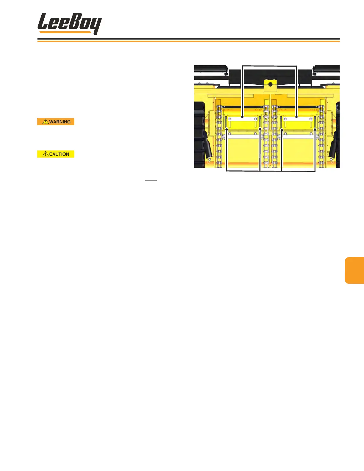
Adjustment Bolts
Conveyor Adjustment Plates
Figure 5-6. Conveyor Flight Chain Adjustment Bolts
Use the following procedure to make this adjustment on
both sides of the conveyor:
1. Move front of paver onto a ramp so you can get
underneath the front of the paver.
2. Loosen the two bolts on each conveyor adjustment
plate. (Figure 5-6)
3. Loosen the jam nuts in front of the adjustment bolts.
4. Turn each adjustment bolt alternately the same
amount. For example, turn one bolt one half turn,
then the other bolt one half turn, etc.
5. Continue alternating tightening until the ight chains
are tight. (The pressure on the chain will be notice-
able as the bolts are tightened.)
NOTE: Drag chains should be 1/2-inch away from
rear frame channel.
6. After the conveyor chain tension is set, retighten
locknuts and bolts holding the ight chain assembly.
7. Repeat steps 1 through 4 for the opposite side.