Maintenance
LeeBoy 8608 Commercial Paver5-34
Hydraulic Pumps/Motor Hydraulic Pumps/Motor
Installation Start-Up ProcedureInstallation Start-Up Procedure
Pre-StartPre-Start
If the hydraulic system is down as a result of a major
component failure:
1. Drain and clean the tank and system components
(hoses, valves, ttings and cooler) to ensure it is
free from metallic debris and other contamination.
Failure to do so may result in damage to hydraulic
components on start-up.
2. Change all the lters.
3. Change the uid. On large systems where the cost
of changing the uid may be prohibitive, the uid
should be ushed until a cleanliness level of ISO
4406 18/13 or better is achieved.
Installation and Start-UpInstallation and Start-Up
When installing hydraulic pumps or motors, it is
important that the mounting ange makes full contact
with the mounting surface of the application. Mounting
hardware of the appropriate grade and size must be
used:
1. Use Grade 8 socket-head capscrews to attach the
motor.
2. Install lock washer over capscrew.
3. Apply Loctite 243 (blue) to the capscrew threads.
4. Install extra thick, hardened H-D thick washers over
the capscrew.
5. Install the capscrew-hardened washer and lock
washer in the SAE two-bolt ange.
6. Torque the capscrew to the wet torque value
dened for the capscrew grade and size.
It is CRITICAL to use the correct
mounting hardware.
Hubs, pulleys, sprockets and couplings must be
properly aligned to avoid inducing excessive thrust or
radial loads. Although the output device must t the
shaft tightly, a hammer should never be used to install
any type of output device onto the shaft. The port
plugs should only be removed from the motor when the
system connections are ready to be made.
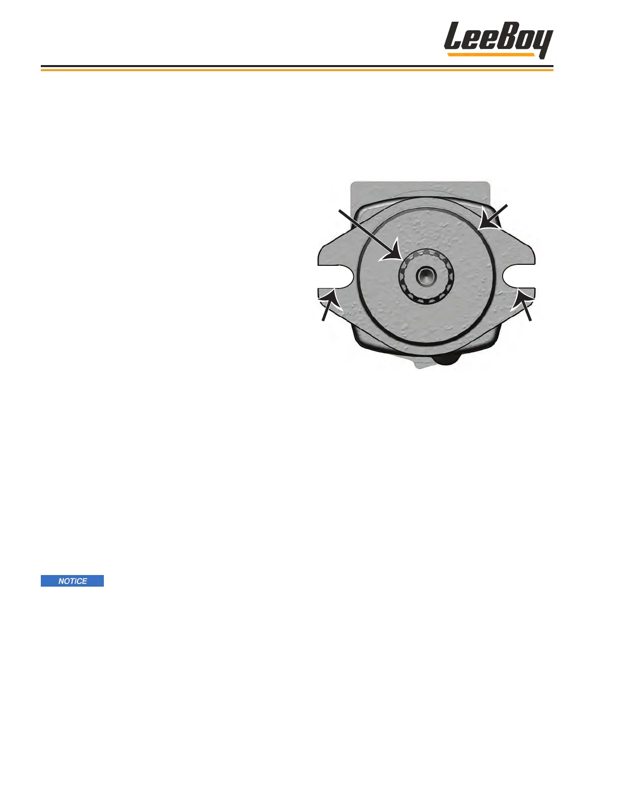
Capscrew
(or Bolt)
+
+
Grease
Shaft
Splines
Capscrew
(or Bolt)
O-Ring
(Required)
Figure 5-36. Hydraulic Motor Mount
To avoid contamination:
• Remove all matter from around the ports of the
motor and the threads of ttings.
• Fill the case of the motor being used (piston-type,
gear motor, gerotor motor, geroller motor or vane
motor) with clean hydraulic uid through the highest
case drain port and connect the case drain line.
Failure to do so will result in damage to the motor
through inadequate lubrication on start-up.
• Units that are mounted vertically with the shaft up
require special attention to ensure the uid level in
the case is high enough to lubricate the front shaft
bearing(s).
Once all system connections are made, the motor
should be run for 15 - 30 minutes at no-load and half-
speed to bleed air from the hydraulic system.