Attention:
• Read “Installation Guidelines” on page 121 and “Safety inspection checklist” on page 122 to ensure that
you work safely.
• Touch the static-protective package that contains the drive to any unpainted metal surface on the server;
then, remove the drive from the package and place it on a static-protective surface.
Watch the procedure. A video of the installation and removal process is available:
• YouTube:
https://www.youtube.com/playlist?list=PLYV5R7hVcs-BXei6L6c05osQVLt4w5XYx
• Youku: https://list.youku.com/albumlist/show/id_59636529
Procedure
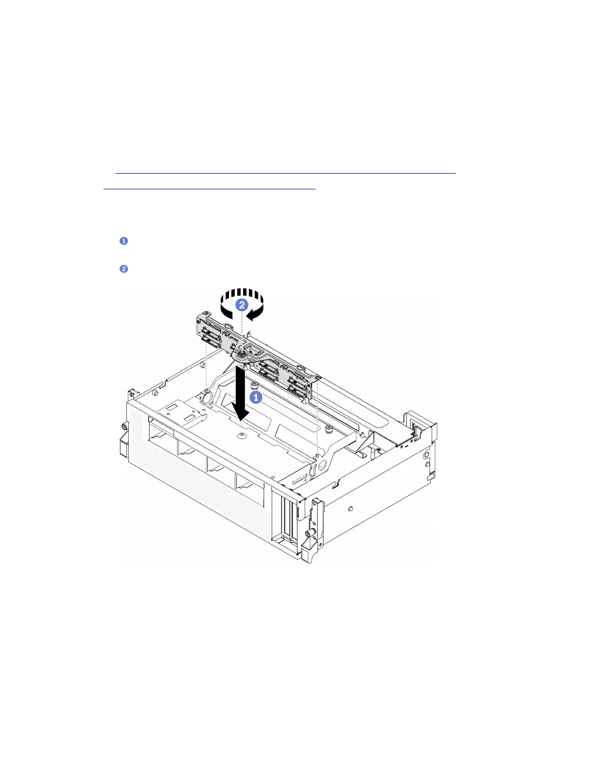
Step 1. Installing the 2.5-inch drive backplane module.
a.
Align the guide holes on the drive backplane module with the guide pins on the 2.5-inch
drive assembly; then, place the drive backplane module onto the assembly.
b.
Fasten the thumbscrew to secure the drive backplane module to the assembly.
Figure 205. Installing the 2.5-inch drive backplane module
After you finish
1. Reconnect the power and signal cables to the 2.5-inch drive backplane.
2. Reinstall the 2.5-inch hot-swap drive or drive bay filler (if any). See “Install a 2.5-inch hot-swap drive” on
page 265.
3. Complete the parts replacement. See “Complete the parts replacement” on page 328.
272
ThinkSystem SR670 V2 Maintenance Manual

 Loading...


