Application Manual CDA3000
4-55
4 Application data sets
1
2
3
4
5
6
A
DE
EN
FR
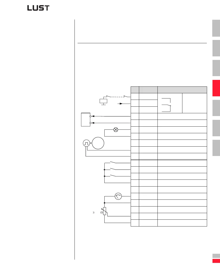
4.6.2 M-S_2
Master drive with encoder evaluation
Preset 2 for Master/-Slave operation
(1) The encoder is evaluated only in control mode FOR.
For notes on the encoder see section 6.3.1 “_79 EN-Encoder evaluation”.
Figure 4.39 Control terminal assignment with ASTER = M-S_2
Function Application
• Speed synchronism of several drives
with programmable transmission
ratio
• Inverter module is master
• Digital guide value input
• Encoder evaluation
• Replacement of mechanical gears
and line shafts (not angle-synchro-
nous)
• Winding drive
• Drafting equipment
• Trolley drive
X2 Des. Function
20 OSD02/14
Relay contact
for “Ready”
message
19 OSD02/11
18 OSD02/12
17 DGND Digital ground
16 OSD01 Slave interface
15 OSD00 “Standstill” message
14 DGND Digital ground
13
U
V
Auxiliary voltage 24 V
12 ISD03 Encoder track B
11 ISD02 Encoder track A
10 ISD01 Start/Stop anti-clockwise
9 ISD00 Start/Stop clockwise
8 ENPO Power stage hardware enable
7
U
V
Auxiliary voltage 24 V
6
U
V
Auxiliary voltage 24 V
5 OSA00 Actual frequency 0 ... FMAX
4 AGND Analog ground
3 ISA01 Not assigned
2 ISA00 Reference -10 V ... + 10 V
1
U
R
Reference voltage 10V, 10mA
H1
ENPO
STL
STR
N1
-
+
DGND
Slave
X2/10
0 ... 10 V
R1
10 k
M
3~
N2
B
(1)
A
+24V
K0
14
11
12

 Loading...
