262335 58 Revision A
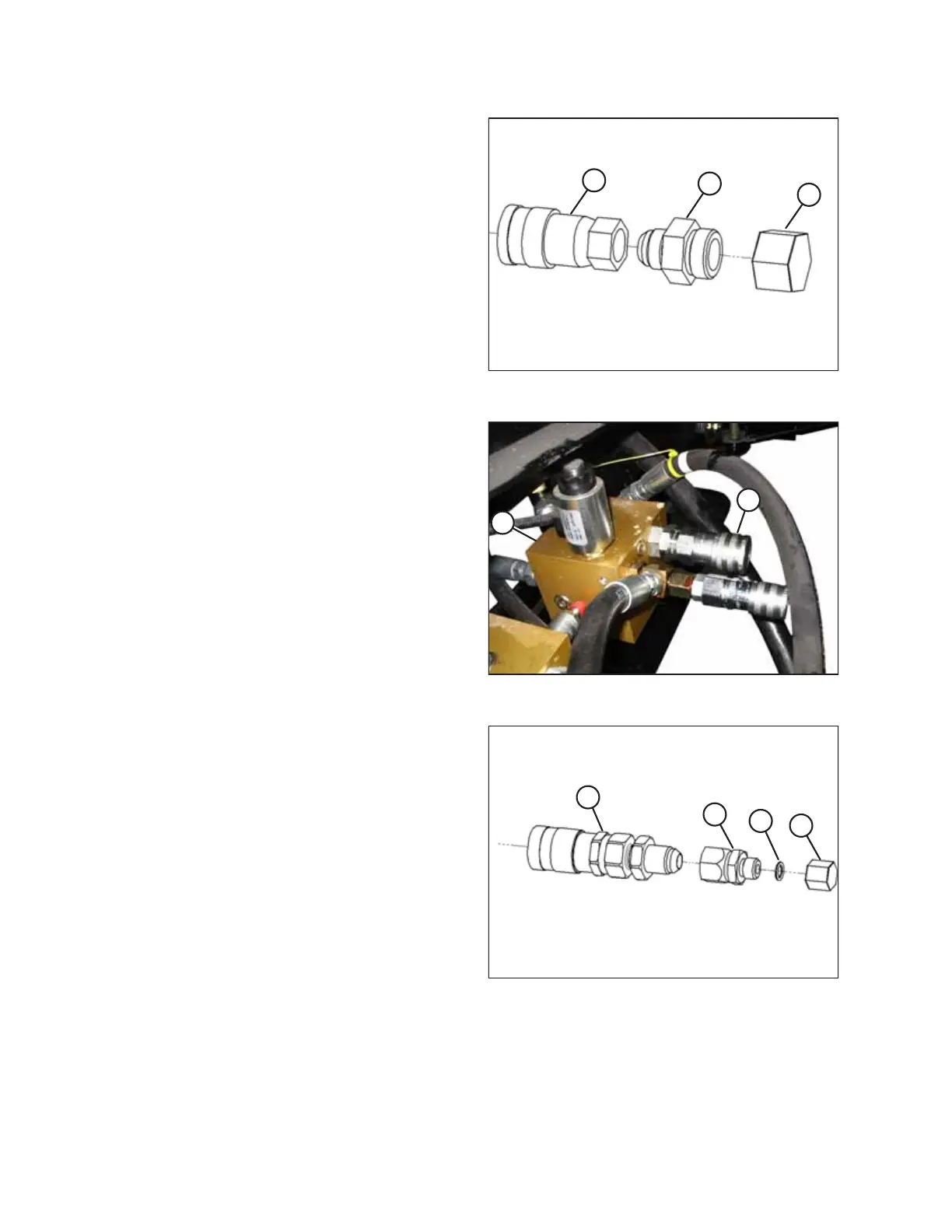
Figure 3.104: Large Coupler Assembly
4. Remove and discard cap (C) and adapter fitting (B) with
O-ring from the large coupler (A).
Figure 3.105: Manifold Configured for Auger Header
5. Install large coupler (A) onto the fitting at port R1 on
manifold (B).
IMPORTANT:
Make sure the O-ring is on JIC threads in port R1 to ensure
a proper seal with coupler (A). If the O-ring is missing, reuse
the O-ring from the discarded adapter fitting in Step 4,
page 58.
Figure 3.106: Small Coupler Assembly
6. Remove and discard cap (A), O-ring (B), and adapter
fitting (C) from small coupler assembly (D).
ASSEMBLING THE MACHINE