262335 70 Revision A
Figure 3.131: Adjusted Configuration – M100, M105,
and M205
8. Reconnect the hoses as follows:
a. Reroute hose (E) behind hose (A) and (F) to hose (C)
and connect tee (B) to the lower port fitting.
b. Reroute hose (C) above hose (E) and (F) and connect
hose (C) to tee (B). Tighten hose (C).
c. Loosen the 45° fittings at both ports. This allows room
for wrenches when tightening tee (B) to the lower port.
d. Connect hose (A) to the upper port fitting as shown
and check the orientation of the 45° fitting.
NOTE:
Ensure that hose (A) is routed in front of hose (C) and
hose (E).
e. Confirm the orientation of the upper port 45° fitting,
back-off tee (B), and tighten the upper port fitting in
the position determined. Tighten hose (A).
f. Check the orientation of the lower port 45° fitting and
tighten it.
g. Connect tee (B) to the lower port 45° fitting and
tighten it.
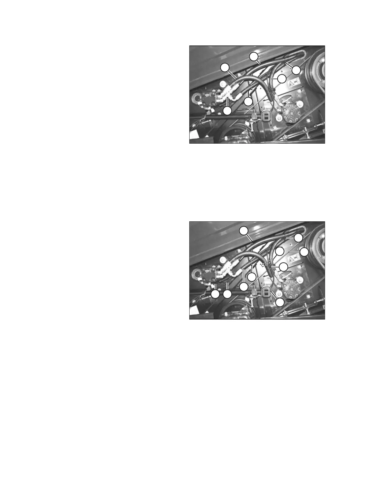
Figure 3.132: Adjusted Configuration – M100, M105,
and M205
9. Secure the hose routing with cable ties (A) as shown.
IMPORTANT:
Ensure that electrical harness (B) and reel motor case drain
hose (C) are secured to hose (D) and that there is at least
25 mm (1 in.) clearance between hose bundle (E) and knife
drive timing belt (F).
IMPORTANT:
Ensure there is enough clearance between the hoses and
any hardware that may need to be accessed to adjust the
reel or auger.
10. Orient the fittings and, if necessary, use a cable tie to
ensure a minimum clearance of 20 mm (3/4 in.) between
hoses and bolt at location (G).
11. Orient the fittings to provide a minimum of 10 mm (3/8 in.)
clearance between the hoses and unplug the tool at
location (H).
12. Orient the fittings to provide a minimum of 200 mm
(7 7/8 in.) clearance between the end panel and the hoses
in location (J).
ASSEMBLING THE MACHINE