214327 107 Revision B
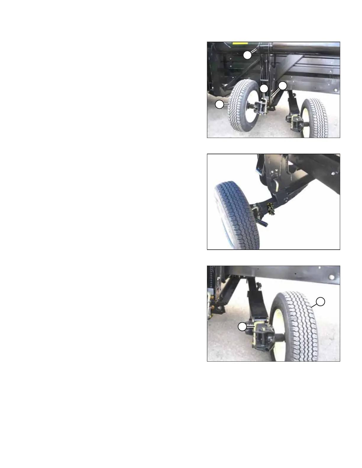
Figure 3.103: Wheel Position
6. Remove pin (A) and install at location (B) to secure the
linkage. Turn the pin to lock.
7. Pull pin (D), swivel wheel (C) counterclockwise 90°, and
release the pin to lock.
Figure 3.104: Left Wheel in Transport Position
8. Ensure the left wheel is in the transport position as shown.
Figure 3.105: Right Rear Wheel
9. Pull pin (A) and swivel right rear wheel (B) clockwise 90°.
OPERATION