214327 149 Revision B
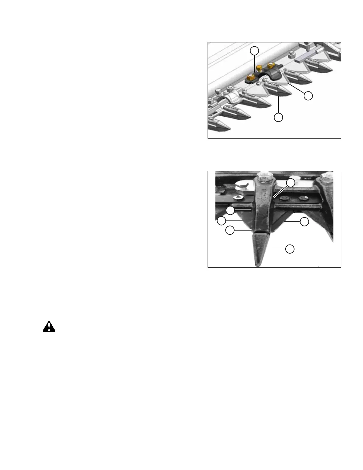
Figure 5.45: Normal Guard Hold-Down
3. Manually stroke the knife to align section (A) under
hold-down (B).
4. At standard guard locations, push knife section (A) down
against guard (C) and measure the clearance between hold-
down (B) and knife section (A) with a feeler gauge. The
clearance should be 0.1–0.6 mm (0.004–0.024 in.).
5. If necessary, refer to Adjusting Pointed Guard Hold-Downs,
page 149.
Double knife:
Figure 5.46: Double-Knife Center Guard Hold-Down
6. Manually stroke the knife to align sections (A) and (C) under
center hold-down (B).
7. Measure between knife sections (A) and (C) with a feeler
gauge. The clearances should be as follows:
• At tip of hold-down: 0.1–0.4 mm (0.004–0.016 in.)
• At rear of hold-down: 0.1–1.0 mm (0.004–0.040 in.)
8. If necessary, refer to Adjusting Hold-Down Clips at Double-
Knife Center Pointed Guard, page 150.
Adjusting Pointed Guard Hold-Downs
This procedure is applicable to formed sheet metal hold-downs. Do NOT use this procedure for the hold-down at the
center guard position where knives overlap on double-knife headers. For center guard, refer to .
DANGER
To prevent bodily injury or death from the unexpected startup of the machine, always stop the engine and remove the
key before adjusting the machine.
MAINTENANCE AND SERVICING