214327 144 Revision B
Figure 5.36: Pointed Guards
3. Remove two nuts (B) and bolts attaching guard (A) and
hold-down (C) (if applicable) to the cutterbar.
4. Remove guard (A), hold-down (C) (if applicable), and plastic
wearplate (if installed).
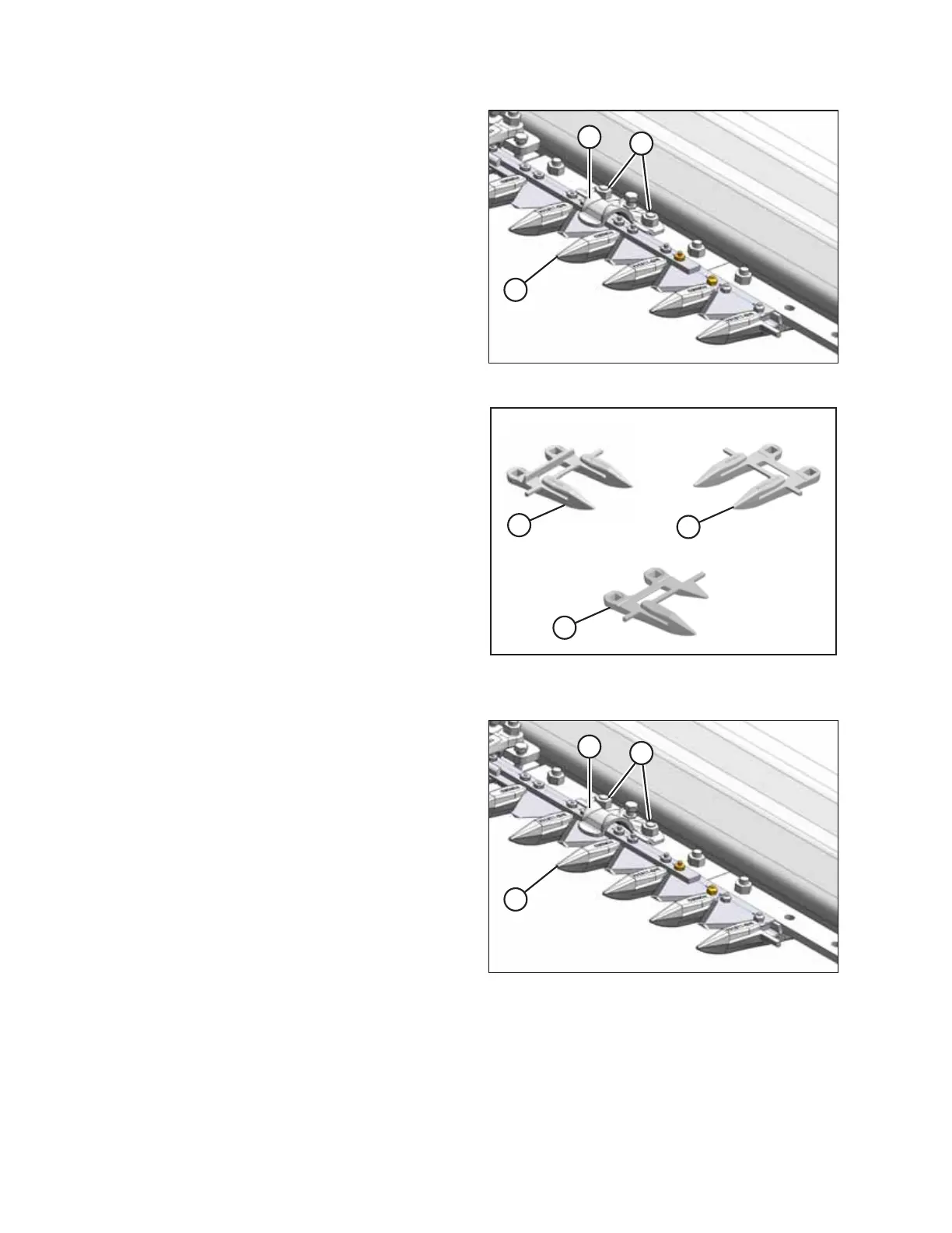
Figure 5.37: Pointed Guards
A - Normal B - Drive Side C - Half Guard (End)
IMPORTANT:
The first four outboard guards (B) on the drive sides of the
header do NOT have ledger plates. Ensure proper
replacement guards are installed at these locations.
Figure 5.38: Pointed Guards
5. Position new guard (A), hold-down (C) (if applicable), and
plastic wearplate (if applicable) onto the cutterbar. Secure
with two nuts (B) and bolts, but do NOT tighten.
6. Check and adjust the clearance between the hold-downs
and the knife. For instructions, refer to .
NOTE:
The guard at the center of a double-knife header (where
the two knives overlap) requires a different replacement
procedure. For instructions, refer to Steps 8, page 145
through 12, page 145.
Replacing center guards
7. Shut down the engine, and remove the key from the ignition.
MAINTENANCE AND SERVICING