214327 193 Revision B
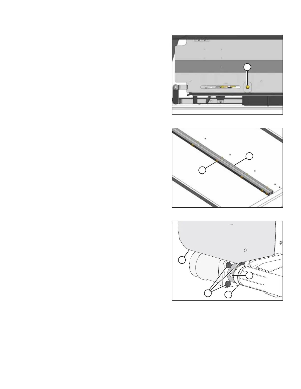
Figure 5.132: Tensioner
6. Loosen the draper by turning adjuster bolt (A)
counterclockwise.
Figure 5.133: Draper Joint
7. Remove connectors (B), screws (A), and nuts from the
draper joint to uncouple the draper.
8. Pull the draper off the drive roller.
Figure 5.134: Drive Roller
9. Align the set screws with hole (A) in the guard. Remove the
two set screws holding the motor onto the drive roller.
NOTE:
The set screws are 1/4 turn apart.
10. Remove four bolts (B) securing the motor to the drive roller
arm.
NOTE:
It may be necessary to remove plastic shield (C) to gain
access to the top bolt.
MAINTENANCE AND SERVICING