214327 235 Revision B
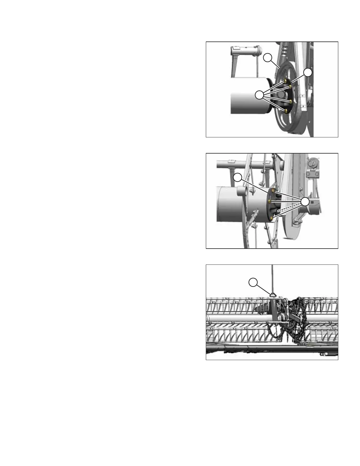
Figure 5.227: U-Joint
1. Position U-joint flange (B) onto driven sprocket (C) as
shown. Install six bolts (A) and hand-tighten them. Do NOT
torque the bolts.
Figure 5.228: U-Joint
2. Position the right reel tube against the reel drive and
engage the stub shaft into the U-joint pilot hole.
3. Rotate the reel until the holes in the end of the reel tube
and U-joint flange (B) line up.
4. Apply medium-strength threadlocker (Loctite
®
243 or
equivalent) to four 1/2 in. bolts (A) and secure them with
lock washers.
5. Torque the bolts to 102–115 Nm (75–85 lbf∙ft).
Figure 5.229: Supporting Reel
6. Remove temporary reel support (A).
7. Install the drive cover. For instructions, refer to Installing
Reel Drive Cover, page 228.
MAINTENANCE AND SERVICING