214327 276 Revision B
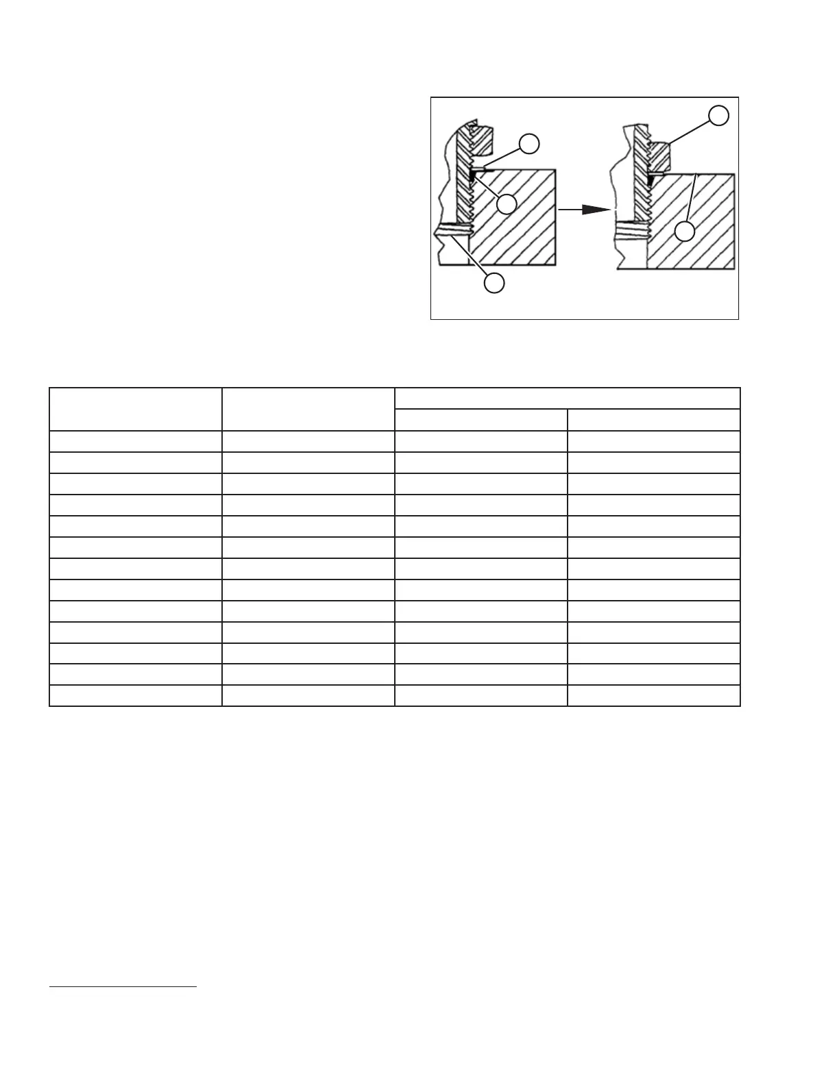
Figure 8.12: Hydraulic Fitting
5. Install fitting (B) into the port until backup washer (D) and
O-ring (A) contact part face (E).
6. Position the angle fittings by unscrewing no more than
one turn.
7. Turn lock nut (C) down to washer (D) and tighten it to the
torque value indicated in the table. Use two wrenches, one
on fitting (B) and the other on lock nut (C).
8. Verify the final condition of the fitting.
Table 8.12 O-Ring Boss (ORB) Hydraulic Fittings – Adjustable
SAE Dash Size
Thread Size (in.)
Torque Value
58
Nm
lbf·ft (*lbf·in)
-2
5/16–24
6–7 *53–62
-3
3/8–24
12–13 *106–115
-4
7/16–20
19–21 14–15
-5
1/2–20
21–33 15–24
-6
9/16–18
26–29 19–21
-8
3/4–16
46–50 34–37
-10
7/8–14
75–82 55–60
-12
1 1/16–12
120–132 88–97
-14
1 3/8–12
153–168 113–124
-16
1 5/16–12
176–193 130–142
-20
1 5/8–12
221–243 163–179
-24
1 7/8–12
270–298 199–220
-32
2 1/2–12
332–365 245–269
REFERENCE
58. Torque values shown are based on lubricated connections as in reassembly.