M A E D A Mini-Crawler Crane Section 4 – OUTRIGGER SETTING
9/2020 MC285CB-3 4-45
3. Insert the position pin (4) into the hole
where the seals “Standard” are aligned.
NOTICE: Position pin has a ball chain for
prevention of loss. Make sure that the ball chain
is not caught by or crossing the top of the frame.
If it is, the position pin will not go all the way into
the pin hole of the rotary and may come off.
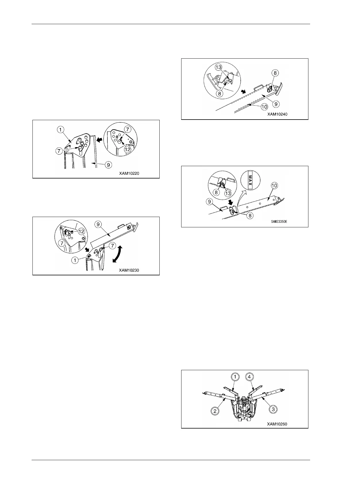
4. Remove the snap pin (12) at the end of the
position pin (7) of the linkage bracket (1)
and pull out the pin.
Fig. 4-108
5. Lift up the top box (9) and align the hole of
the top box with the position of the
outermost hole on the linkage bracket (1).
Fig. 4-109
NOTICE: The position of the outermost hole on
the linkage bracket means the one that has the
seal “MAX” affixed to it.
6. Insert the position pin (7) into the outermost
hole on the linkage bracket (1) and retain it
with the snap pin (12) at its end.
NOTICE: If you use the outriggers by inserting
the pin into any hole other than the one with a
sticker “Extended to maximum” at the pin of the
coupled bracket, operate the machine in
accordance with the rated total load for the
"Other than MAX" outrigger position in “RATED
TOTAL LOAD CHARTS” on page 3-13.
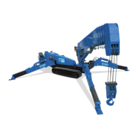
7. Remove the snap pin (13) at the end of the
position pin (8) of the top box (9) and pull
out the position pin.
Fig. 4-110
8. Pull out the inner box (10) from the top box
(9) and align the hole on the top box with the
position of the innermost hole on the inner
box.
Fig. 4-111
NOTICE: The position of innermost hole on inner
box, means the one that meets the top box hole
when the seal “MAX” affixed to the side of inner
box is totally exposed.
9. Insert the position pin (8) into the hole of the
top box (9) and retain it with the snap pin
(13) at its end.
NOTICE: When the outrigger is set with the pin
inserted to any hole other than that of "MAX"
extension, work should be performed in
accordance with the rated total load for the
"Other than MAX" outrigger position in “RATED
TOTAL LOAD CHARTS” on page 3-13.
10. Prepare the other three outriggers in the
same manner.
Fig. 4-112