Installation and User Manual
52
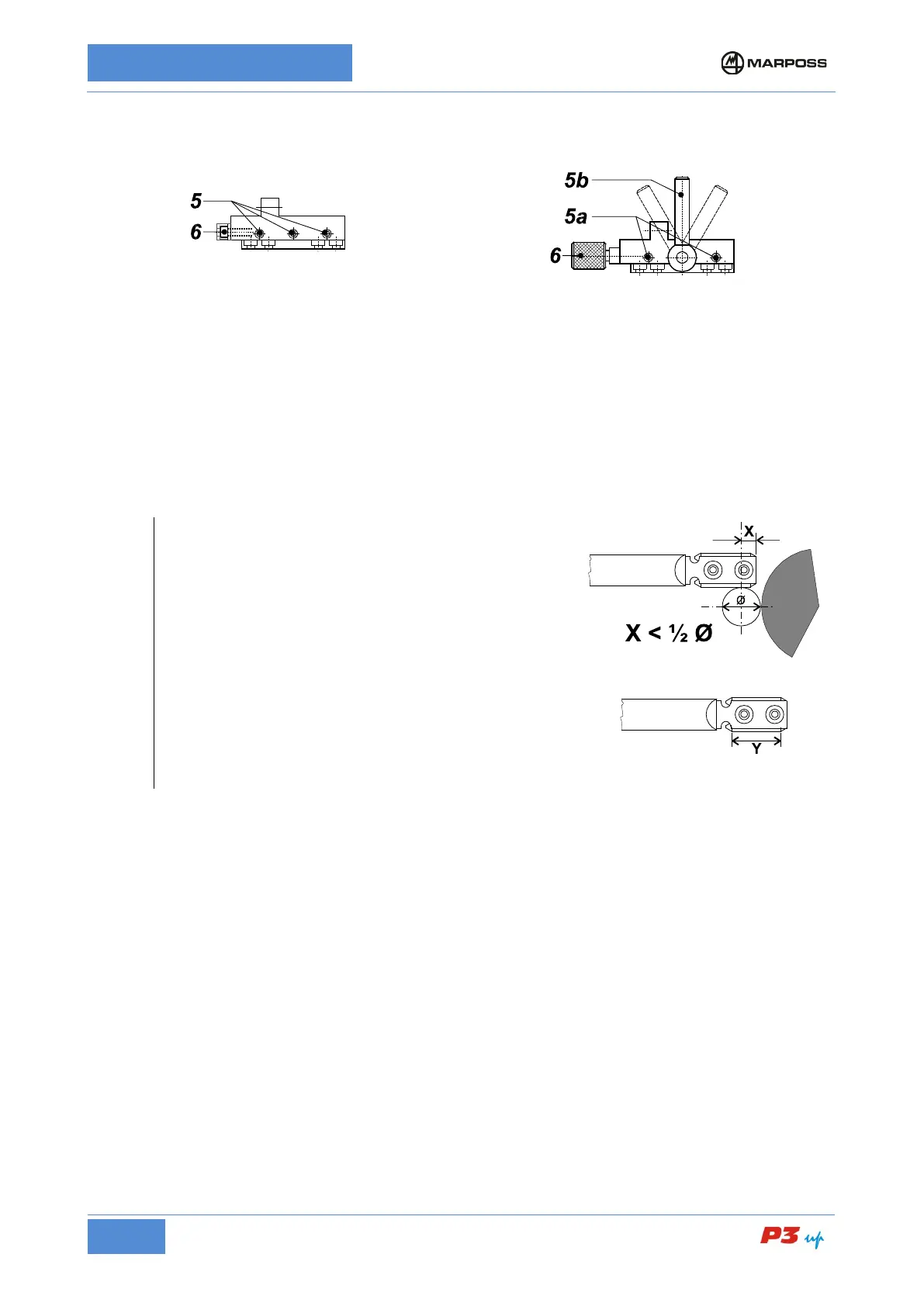
Head support – Slide with
retaining screws
Loosen screws 5 maintaining the friction on them.
Head support – Slide with
locking handle
Release the movement of the head support by
adjusting the handle 5b.
Adjust screws 5a so as to allow frictioned movement of
Rotate the screw/knob 6 moving the measuring head forwards/backwards(*) until it reaches the position
corresponding to the maximum measurement readout (contacts on diameter); refer to the diameter display
on the electronic unit.
Tighten screws 5.
Lock the head support with handle 5b.
Rotate the screw/knob 6 in the opposite direction to release it and avoid tensioning the adjustment system.
Measurement heads with bar contacts
When positioning the contacts lengthwise on the workpiece
(measuring head back/forth movement) pay attention to
value X.
Value X shall be less than ½ the diameter to be measured
in order to prevent a collision between stylus and wheel.
Measuring grooved parts
When measuring grooved parts with interruptions ≤
the working portion Y of the contact should be greater than
the interruption sector. If there be interruptions with
different lengths, consider the longest one.
Interruptions >10 mm must be considered one at a time.
• Adjusting the Upper Contact
(Refer to the examples in Figure 12: Measurement head with two ball probes, Figure 13: UNIMAR
measurement heads with ball probes, Figure 14: Measurement head with two bar probes, and Figure 15:
UNIMAR measurement heads with bar probes)
1. Loosen screw 1 maintaining the friction on it.
2. Rotate screw 2 (knob or hexagonal head screw) so that the upper contact touches the master workpiece
and the measurement value that appears on the gauge is around zero (± 10 µm).
3. After completing these operations, tighten screw 1 and rotate screw 5.08 cm the opposite direction until
it is released in order to avoid tensioning the adjustment system.
• Adjusting the Lower Contact
(Refer to the examples in Figure 12: Measurement head with two ball probes, Figure 13: UNIMAR
measurement heads with ball probes, Figure 14: Measurement head with two bar probes, and Figure 15:
UNIMAR measurement heads with bar probes)
1. Loosen screw 3 maintaining the friction on it.
2. Rotate screw 4 (knob or hexagonal head screw) so that the lower contact touches the master workpiece
and the measurement value that appears on the gauge is around zero (± 10 µm).
3. After completing these operations, tighten screw 3 and rotate screw 10.16 cm the opposite direction until
it is released in order to avoid tensioning the adjustment system.