Installation and User Manual
51
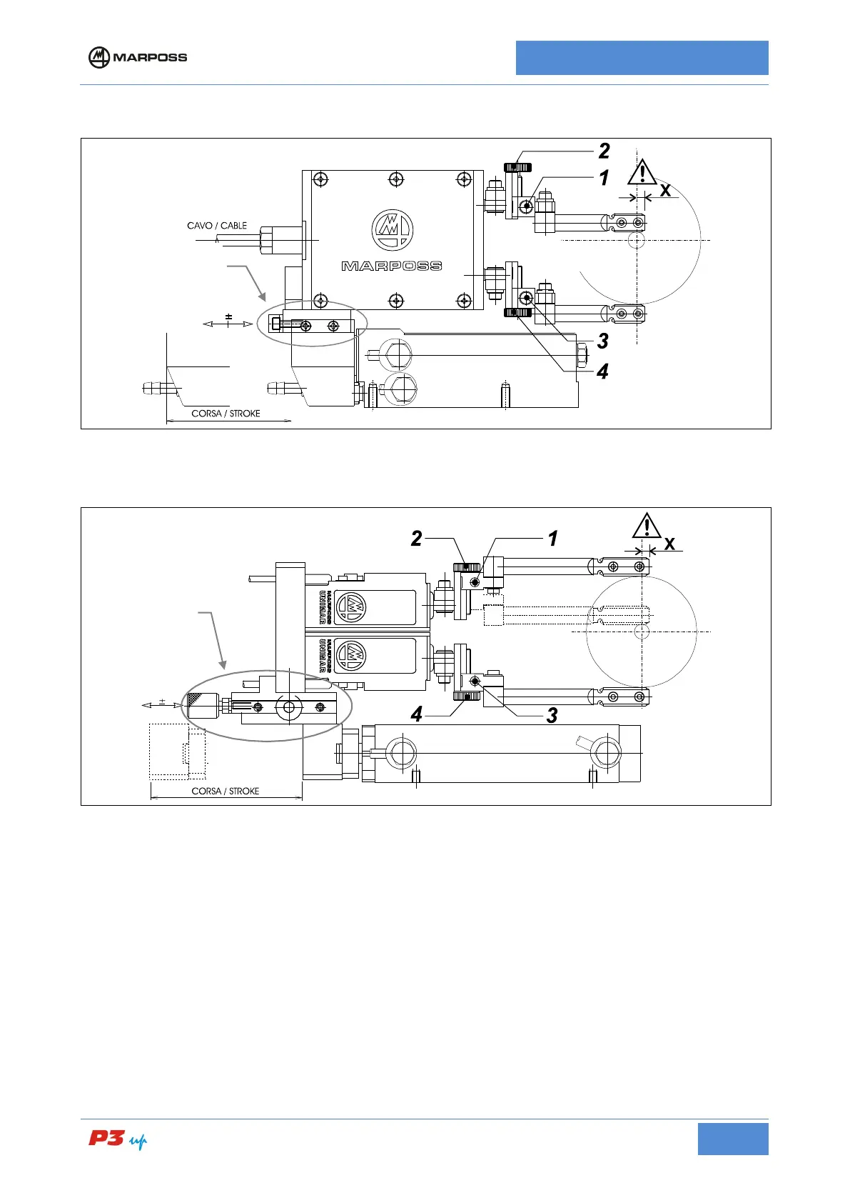
• Measurement head with two bar probes
Figure 14: Measurement head with two bar probes
• Unimar Measurement heads with bar probes
Figure 15: UNIMAR measurement heads with bar probes
• Measurement head diameter alignment
(Refer to the examples in Figure 12: Measurement head with two ball probes, Figure 13: UNIMAR
measurement heads with ball probes, Figure 14: Measurement head with two bar probes, and Figure 15:
UNIMAR measurement heads with bar probes)
1. Place a ground workpiece either on the spindle or between the tips.
2. Loosen screws 1 and 3 to allow a frictioned movement of the guides.
3. Rotate screws 2 and 4 (knob or hexagonal head screw) bringing the styli to a position allowing to insert
the head in measuring position in safe conditions (without impact with the workpiece).
4. Bring the measuring head to measuring position.
5. Rotate screws 2 and 4 to so that the contacts are touching the workpiece and are within range (refer to
the readout of the individual transducers on the electronic unit).
6. Tighten screws 1 and 3.
7. Now act on the head holding unit.
Unit
Unit