188 CONTENTS
20.2.8.2 Initial situation and settings
Generally, line scan cameras are suitable for inspections of moving, continuous materials. In order that the line
scan camera acquires the line at the right time, an incremental encoder (p. 227), for example, at a conveyor belt
triggers the line scan camera. Normally, an incremental encoder (p. 227) does this using a specific frequency like
1:1 which means that there is a signal for every line. However, during the adjustment of a line trigger application or
while choosing a specific incremental encoder you have to keep the specific frequency in mind.
Note
Using timers and counters (p. 113) it is possible to skip trigger signals.
In line scan mode, the camera adds the single lines to one image of the height of max. 1024 or 1200 lines (according
to the used sensor). The images are provided with no gap.
Note
While using the line scan mode with a gray scale sensor, one trigger signal will lead to one acquired image
line. Using a color sensor, one trigger signal will lead to two acquired image lines.
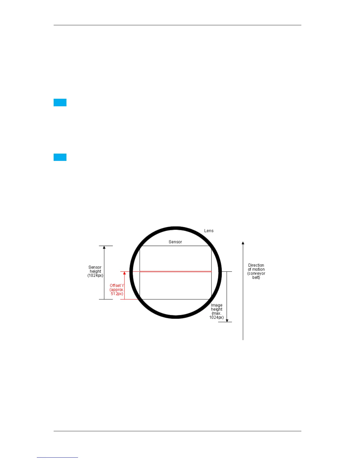
Due to aberrations at the edges of the lens, you should set an offset in the direction of Y ("Offset Y", see the
following figure), generally around the half of the sensor's height (a.k.a. sensor's Y center). With Offset Y you can
adjust the scan line in the direction of motion.
Figure 1: Sensor's view and settings with a sensor with max. height of 1024 pixels/lines (e.g. -x02e / -1013)
20.2.8.2.1 Scenarios
With regards to the external trigger signals provided by an incremental encoder (p. 227), there are two possible
scenarios:
1. A conveyor belt runs continuously and so does the incremental encoder (p. 227), or - like in a reverse
vending machine,
MATRIX VISION GmbH