20.2 Introducing acquisition / recording possibilities 189
2. a single item is analyzed and the conveyor belt and so the incremental encoder (p. 227) stops after the
inspection and restarts for the next item.
In the first scenario you can use the standard settings of the MATRIX VISION devices. Please have a look at the
sample Sample 2: Triggered line scan acquisition with a specified number of image blocks and pausing
trigger signals (p. 191) scan_Sample "Triggered line scan acquisition with exposure time of 250 us" which shows
how you can set the line scan mode with continuous materials and signals from the encoder. However, it is absolutely
required that the external trigger is always present. During a trigger interruption, controlling or communication to
the camera is not possible.
In the second scenario, the external trigger stops. If there is a heartbeat functionality in the system (e.g. with GigE
Vision), there can be a halt of the system. Please have a look at the sample Triggered line scan acquisition with
a specified number of image blocks and pausing trigger signals (p. 189) which shows how you can handle
pausing trigger signals.
20.2.8.3 Sample 1: Triggered linescan acquisition with exposure time of 250 us
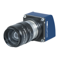
This sample will show you how to use the line scan mode of the sensors -1013 (p. 336) and -1013GE (p. 336) using
an external trigger provided by an incremental encoder (p. 227) which sends a "trigger for every line" (1:1)
Note
You can also use the sensor -1020 (p. 339) . However, the sensor is slower due to the higher number of pixels.
In this sample, we chose an exposure time of "250 us" and to ease the calculations we used "1000 px image
height".
Note
To get suitable image results, it might be necessary to increase the gain or the illumination.
These settings result in a max. "frame rate" of "2.5 frames per second".
To adjust the opto-mechanics (focus, distance, illumination, etc.), you can use the area mode of the sensor. That's
a main advantage of an area sensor with line scan mode compared to a line scan camera!
You will need the following pins of the mvBlueFOX3:
Pin. Signal (Standard version) Description
1 GND Common ground
2 12V .. 24V Power supply
4 Opto DigIn0 (line4) The output signal A of the incremental encoder
20.2.8.3.1 Setting the application in wxPropView
Summary of our sample:
Property name wxPropView Setting GenICam Control (p. 107) Comment
Device Scan Type line scan Device Control
Height (in pixels) 1000 Image Format Control
MATRIX VISION GmbH