230 CONTENTS
20.4.2.2 Programming the pulse width modulation
You will need two timers and you have to set a trigger.
• Timer1 defines the interval between two triggers.
• Timer2 generates the trigger pulse at the end of Timer1.
The following sample shows a trigger
• which is generated every second and
• the pulse width is 10 ms:
#include <mvIMPACT_CPP/mvIMPACT_acquire.h>
#include <mvIMPACT_CPP/mvIMPACT_acquire_GenICam.h>
...
// Master: Set timers to trig image: Start after queue is filled
GenICam::CounterAndTimerControl catcMaster(pDev);
catcMaster.timerSelector.writeS( "Timer1" );
catcMaster.timerDelay.write( 0. );
catcMaster.timerDuration.write( 1000000. );
catcMaster.timerTriggerSource.writeS( "Timer1End" );
catcMaster.timerSelector.writeS( "Timer2" );
catcMaster.timerDelay.write( 0. );
catcMaster.timerDuration.write( 10000. );
catcMaster.timerTriggerSource.writeS( "Timer1End" );
See also
Counter And Timer Control (p. 113)
Note
Make sure the Timer1 interval must be larger than the processing time. Otherwise, the images are lost.
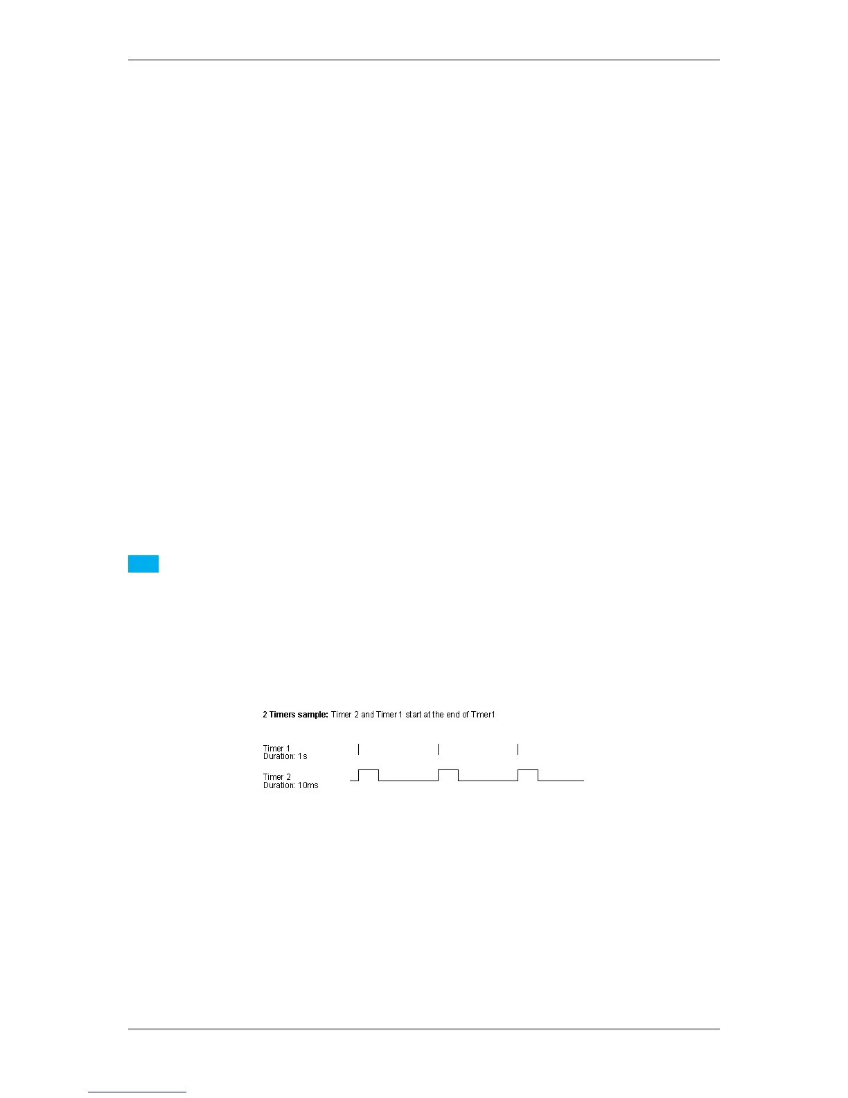
Now, the two timers will work like the following figure illustrates, which means
• Timer1 is the trigger event and
• Timer2 the trigger pulse width:
Figure 1: Timers
The timers are defined, now you have to set the digital output, e.g. "Line 0":
// Set Digital I/O
GenICam::DigitalIOControl io(pDev);
io.lineSelector.writeS( "Line0" );
io.lineSource.writeS( "Timer2Active" );
See also
Digital I/O Control (p. 120)
This signal has to be connected with the digital inputs of the application.
MATRIX VISION GmbH