Page 107
Appendix| Pin Assignment Sensor Cable
optoNCDT 1700
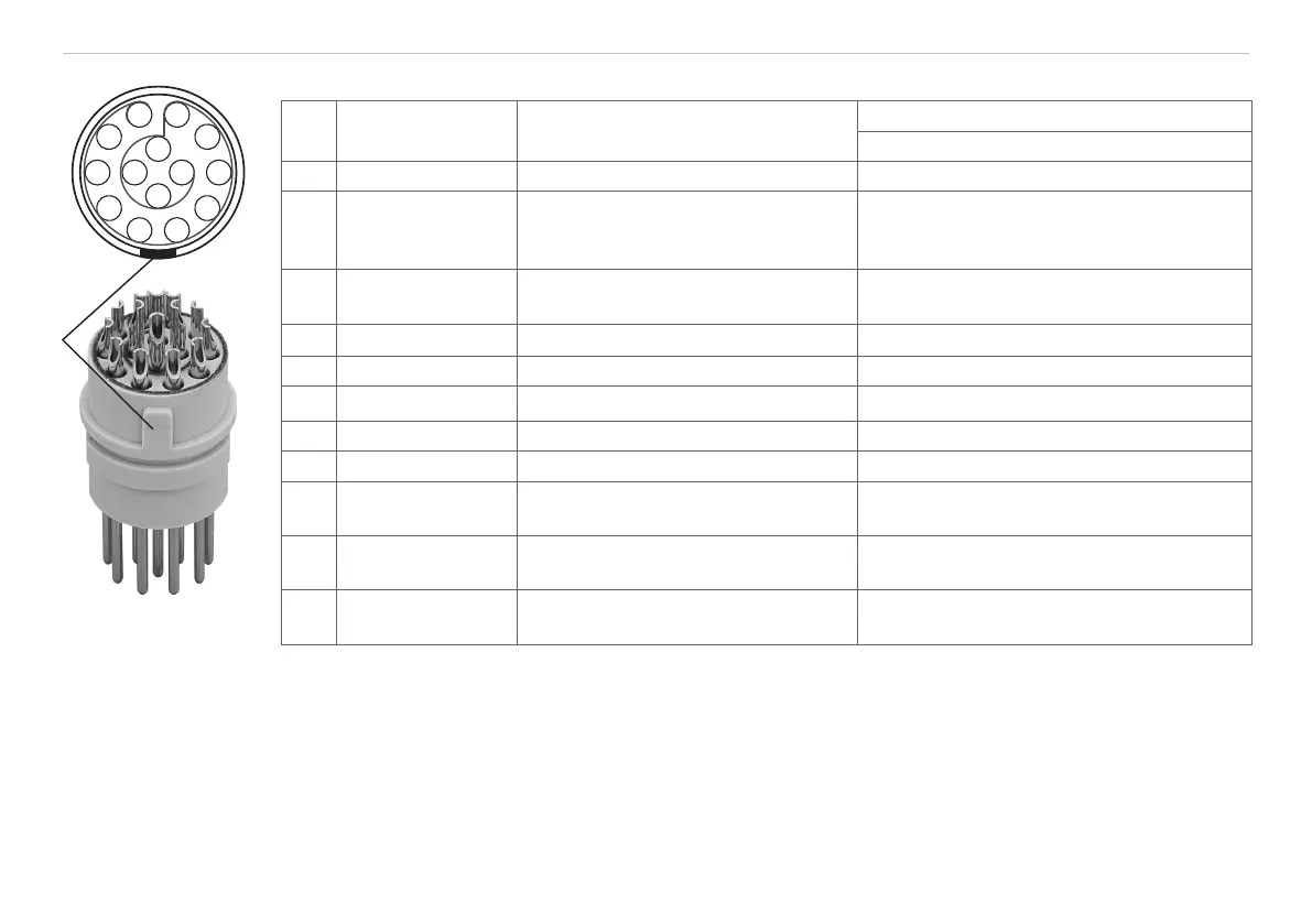
A 4 Pin Assignment Sensor Cable
Pin Designation Characteristics
Color Sensor Cable
PC1700-x
5 +U
B
Power supply (11 ... 30 VDC) red
6 GND
System ground for power supply
switch signals (Laser on/off, Mid-
point, Limits)
black
13 Analog output
Current 4 ... 20 mA or
Voltage 0 ... 10 V
Coaxial inner conductor, white, see Fig. 55
14 AGND Reference potential for analog output Coaxial screening, black, see Fig. 55
9 Laser on/off Switching input Laser ON / OFF red and blue
10 Zero Switching input for reset white and green
8 Switching output 1 Error or limit output gray and pink
7 Switching output 2 Limit output violet
3
4
Sync +
1
Sync
-
1
Symmetrical synchron output
(Master) or input (Slave)
blue
pink
1
2
Tx +
Tx -
RS422 - Output (symmetric)
green
brown
12
11
Rx +
Rx -
RS422 - Input (symmetric)
gray
yellow
Plug connector:
ODU MINI-SNAP, 14-pin, series B, Dimension 2, Code 0, IP 68
More information on www.odu.de
1) Used as trigger inputs in mode “Triggering“, see Chap. 6.14.
1
2
3
4
5
6
7
8
9
10
11
12
13
14
View: Solder-pin side
male cable connector,
insulator