Page 59
Serial Interface RS422
optoNCDT 1700
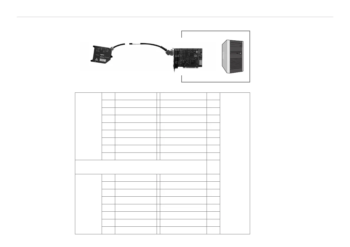
8. Serial Interface RS422
PC1700-x/IF2008
IF2008 PC
Fig. 42 System structure to operate the interface card IF2008
Sensor 1
14-pol.
ODU-con-
nector
Pin Signal Signal Pin
IF2008,
X1 and X2,
15-pol.
Sub-D
5 24 V 24 V supply
1
10
12 Rx + (Input) Sensor 1/3 TxD+ 2
11 Rx - (Input) Sensor 1/3 TxD - 1
1 Tx + (Output) Sensor 1/3 RxD+ 4
2 Tx - (Output) Sensor 1/3 RxD - 3
3 Sync + TRG + 6
4 Sync - TRG - 7
6 GND GND 15
When using 3 sensors apply the optional available Y-
adapter cable IF2008-Y.
Sensor 2
14-pol.
ODU con-
nector
5 24 V 24 V supply
1
10
12 Rx + Sensor 2/4 TxD+ 12
11 Rx - Sensor 2/4 TxD - 11
1 Tx + Sensor 2/4 RxD+ 14
2 Tx - Sensor 2/4 RxD - 13
3 Sync + TRG + 6
4 Sync - TRG - 7
6 GND GND 15
Required cables and program
routines
- IF2008
RS422 interface card, for 1
to 4 laser-optic sensors from
the ILD1700 series and 2 en-
coders, including MEDAQlib
programming interface.
- PC1700-x/IF2008
Power supply and output
cable, x = length with 3, 6 or
8 m.
Alternatively, data can be trans-
ferred with the demo software
(ILD1700 Tool) and a RS422
converter to USB, see Chap. 10..
Fig. 43 Pin assignment for two
PC1700-x/IF2008 and IF2008
1) Supply voltage for the con-
nected sensors and encoders,
output current 1.25 A max.