Page 50
Operation
optoNCDT 1700
Although this does not change the measurement frequency, the output rate is reduced by half in this mode.
An unsynchronized slave switches the laser off, sends an accordant error signal.
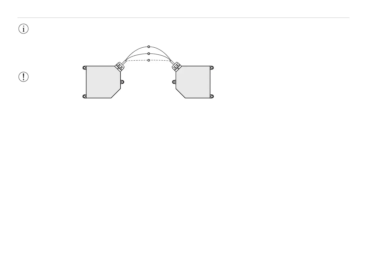
Pin 3, blue
Pin 4, pink
Pin 6,
brown (black)
1
Conductors twisted together in the cable must
be used for synchronization. Terminals with the
same polarity (Sync+ and Sync-) should be
connected.
The optoNCDT1700 contains a terminating
resistor, see Fig. 31, between pin 3 and 4 for line
matching.
Fig. 31 Synchronization of two optoNCDT1700
Synchronization with external signal
If a sensor is synchronized with an external signal the levels of the signal must comply with the LVDS speci-
fications (Low Voltage Differential Signals). Further information, see Chap. 6.14.3. The synchronization
frequency is to maintain with a tolerance of ±1 % of the measurement frequency.
Triggering is done with an accordant hardware only. Use the optional available triggerBOX1700 from
MICRO-EPSILON.
6.12 Exposure Time
At a maximum measurement frequency of 2.5 kHz the CCD element is exposed 2500 times per second. This
gives a predefined maximum exposure time (laser exposure time) of 0.4 ms at this measurement frequency.
The lower the measurement frequency, the longer the maximum exposure time.
The real-time control of the sensor reduces the exposure time in dependency on the amount of light hitting
the CCD element and therefore compensates for reflection changes at the same time, e.g. caused by imprints
on the surface of the object being measured.
IMPORTANT!
The slave sensor
should be operated
unsynchronized as far
as possible!
WARNING!
The synchronous
terminals must never
be connected to the
operating voltage
and/or GND, even
momentarily. Risk of
permanent damage
from overloading!
1) Connect the
ground connectors
(GND, pin 6, black), of
the sensors if the
sensors are not
operated on the same
power supply.