Page 47
Operation
optoNCDT 1700
6.9 Frequency and Output Rate
The measurement frequency defines the number of measurements performed by the sensor per second. The
measurement frequency may be 2.5 kHz, 1.25 kHz, 625 Hz or 312.5 Hz. Details of how to change the
measurement frequency, see Chap. 6.5.
The output rate gives the actual number of measurement values at the sensor output per second. The
maximum output rate can never exceed the measurement frequency.
Output Maximum output rate
The sensor continues to measure internally but holds
back the output until the last measurement value has
been issued in full. The next measurement value is
the last valid value, with other values between being
lost.
Fig. 26 Output rates for the output types
Current Measurement frequency
Voltage Measurement frequency
RS422
Output rate Measurement frequency;
Dependent on the transmission rate
(baud rate) and data format (ASCII-Code).
Calculation of the output rate using the RS422 serial interface:
Output rate = Measuring frequency n
Abbreviations used:
n = Partial factor
int = Integral part of ( )
b = Byte/measurement value
(binary format b=2, ASCII b=6))
MR = Measurement frequency [Hz]
BR = Baud rate [Baud]
n = int (b * 11 * MR / BR) + 1
The values are summarized, see Chap. A 3.
Example:
Measurement frequency = 1250 Hz, ASCII-Format (b=6), Baud rate = 19200 Baud
--> n = int (4.3) + 1 = 5
--> Output rate = 1.25 kHz / 5 = 250 Hz.
IMPORTANT!
Synchronized
sensors must always
be set to the same
measurement
frequency.
Please, see Chap. A 3.
Recommendations:
- Use a high measure-
ment frequency for light
colored and matt ob-
jects to be measured.
- Use a low measure-
ment frequency for
dark or shiny objects to
be measured (e.g.
surfaces covered in
black lacquer), for bet-
ter measurement
results.
6.10 Operation Mode
6.10.1 Error Mode
(Error Control)
In error mode, the switching output 1 is used as
an error output. The switching output 2 remains
inactive. The error mode can be programmed
using both the keypad and the programming
interface.
The error output is activated (conducting to
GND) when:
- the object to be measured is outside the
measurement range, see Fig. 27,
- there is no object to be measured present, or
- if the object to be measured is unsuitable (too
dark, polished metal, insufficiently reflective).
Transparent objects can be penetrated by the
light of the laser and the laser spot unacceptably
enlarged, resulting in unreliable measurements.
This will also trigger the error output.
6.10.2 Switch Mode
(Limit Control)
In switch mode, both switching outputs
are used as limit switches, see Fig. 28.
The individual limits can be programmed using
the digital programming interface, see Chap.
8.5.7, see Chap. 8.5.8.
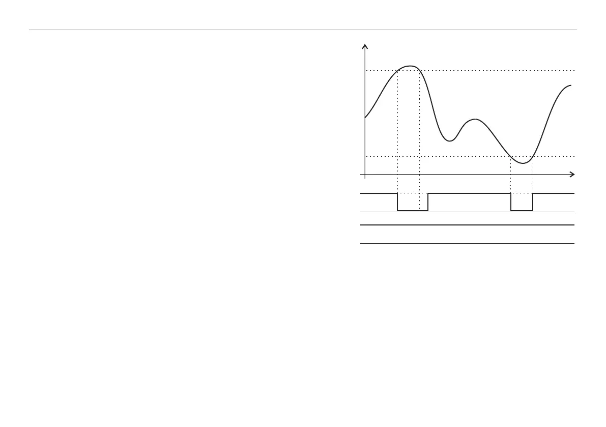
Measured value
EMR
+
GND
+
GND
Switching output 1
Switching output 2
SMR
Time
Fig. 27 Signal sequence for the switching outputs in the
operation mode „Sync error“ and „Trigger error“
Error mode: Setting mid-point only, no limit control
Switch mode: Mastering only, limit control