Page 32
Installation
optoNCDT 1700
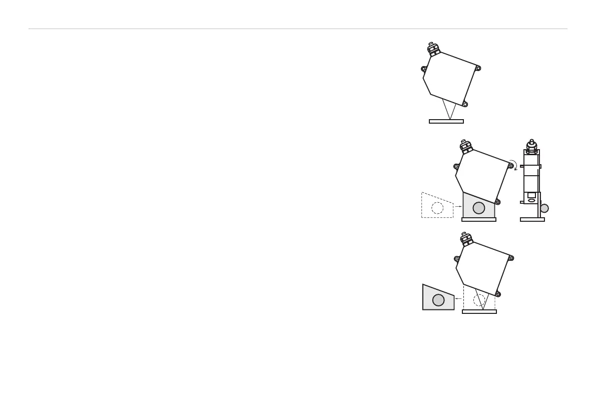
Mounting steps
- Switch on the operating voltage
- Watch the “State“ LED on the top side of the sensor, see Fig. 20.
- Position a shining or mirroring measuring object.
Measuring object
- Move the fit-up aid between sensor and measuring object.
- The “State“ LED illuminates yellow, see Fig. 20.
- Mount the sensor by means of 3 screws type M4.
- Remove the fit-up aid between sensor and measuring object.
5.3 Connector and Sensor Cable
Never bend the sensor cable by more than the bending radius of 60 mm.
The sensor comes with a permanently mounted connection cable of 0.25 m in length. Depending on where
it is installed, a 3 m or 10 m sensor cable has to be attached to the connection cable.
MICRO-EPSILON recommends the use of the PC1700 standard sensor cable with a chain-type cable capabil-
ity.