Page 96
Instruction for Operating
optoNCDT 1700
9.3 Optimizing the Measuring Accuracy
function
enter
select
zero
output
speed
avg
zero
state
default
>5s
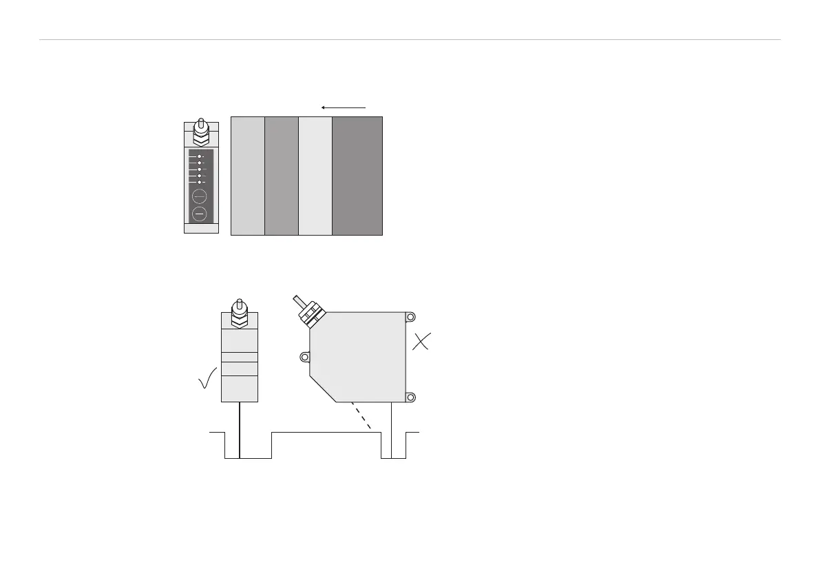
Color strips Direction of movement
Grinding or rolling marks
In case of rolled or polished metals that are
moved past the sensor the sensor plane must
be arranged in the direction of the rolling or
rinding marks. The same arrangement must be
used for color strips, see Fig. 49.
Fig. 49 Sensor arrangement in case of ground or
striped surfaces
Correct
Incorrect
(shadow)
In case of bore holes, blind holes, and edges in
the surface of moving targets the sensor must
be arranged in such a way that the edges do not
obscure the laser spot, see Fig. 50.
Fig. 50 Sensor arrangement for holes and ridges