Page 19
Functional Principle, Technical Data
optoNCDT 1700
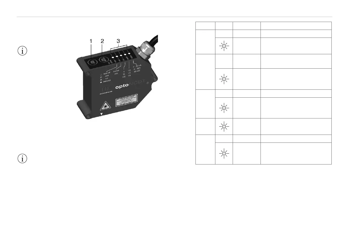
3.5 Control and Indicator Elements
Fig. 4 Keys and LED‘s on the sensor
(1) select/zero key Measurement mode:
Sets analog output to
„Master“ or „Mid-point“, see Chap. 6.7, see
Chap. 6.8.
Setup mode: For changing the sensor
parameters, see Chap. 6.5.
(2) function/enter key
For switching between measurement mode
and setup mode.
(3) LEDs, see Fig. 5.
IMPORTANT!
Keys can be locked
via the serial interface,
see Chap. 8.5.16.
For the meanings of
the LEDs in setup
mode, see Chap. 6.3.
IMPORTANT!
If the function/
enter key is pressed
more than 5 sec, all
para-meters are over-
written by the factory
settings.
LED Color Meaning
output
o Current (4 ... 20 mA)
red
green
Voltage (0 ... 10 V)
Serial (RS422)
speed
o
Measurement frequency
1 = 2.5 kHz
red
green yel-
low
1/2 = 1.25 kHz
1/4 = 625 Hz
1/8 = 312.5 Hz
avg
o Average: 1 (Median: 3)
red
green yel-
low
4 (5)
32 (7)
128 (9)
zero
red
flashing
Mid-point set / mastered
Slave not synchronized
state
o Laser off
red
green yel-
low
Error
O.K.
MMR (midrange)
Fig. 5 Meanings of the LEDs in measurement mode
Note: In measurement mode (factory setting) only the
LED „state“ lights up, subject to the current position of
the object to be measured.