Page 29
Installation
optoNCDT 1700
5.2 Sensor Mounting Direct Reflection
IMPORTANT!
Handle optical
sensors with care!
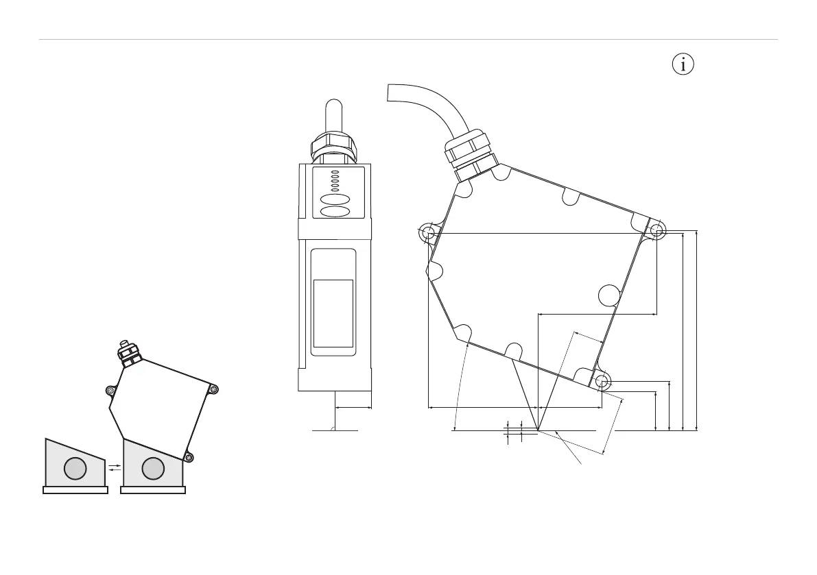
Fig. 15 Accessory to mount the sensor
15
(.59)
90 °
45.6
(1.79)
26.5
(1.04)
13.4
(.53)
49.5 (1.95)
Direct reflecting target
25
(.98)
20 °
1 (.04)
MB 2 (.08)
16.7 (.66)
20.7 (.81)
82.6 (3.25)
83.7 (3.30)
Fig. 16 Dimensional drawings optoNCDT1700-2DR (not to scale)
The sensor is mounted by
means of 3 screws type M4. The
bearing surfaces surrounding the
fastening holes (through-holes)
are slightly raised.
Mount the sensor, that the re-
flected laser light hits the receiver
element, see Fig. 16, see Fig. 17,
see Fig. 18.
Use a fit-up aid to mount the sen-
sor, see Fig. 15.
Legend:
mm (inches)