Page 33
Installation
optoNCDT 1700
The connector and the cable component are marked with red markings which have to be aligned opposite each other before connec-
tion. In addition, they come with guidance grooves to prevent them from being wrongly connected. To release the plug-in connection,
hold the plug-in connector on the grooved grips (outer sleeves) and pull apart in a straight line. Pulling on the cable and the lock nut
will only lock the plug-in connector (ODU MINI-SNAP FP - lock) and will not release the connection. It is important, therefore, that the
cable is never subjected to excessive pull force. If a cable of over 5 m in length is used and it hangs vertically without being secured,
make sure that some form of strain-relief is provided close to the connector. Never twist the connectors in opposite directions to one
another when connected.
Connect the cable shield to the potential equalization (PE, protective earth conductor) on the evaluator (control cabinet, PC housing)
and avoid ground loops.
Never lay signal leads next to or together with power cables or pulse-loaded cables (e.g. for drive units and solenoid valves) in a
bundle or in cable ducts. Always use separate ducts.
Recommended strand cross-section for self-made connection cables: ≥ 0.14 mm² (AWG 25)
i
Disconnect or connect the D-sub connection between RS422 and USB converter when the sensor is disconnected from power
supply only.
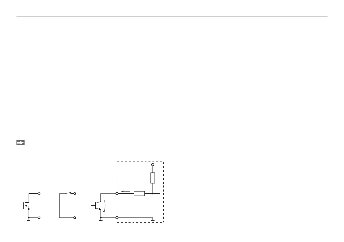
5.4 Switching Inputs Laser On/Off, Setting Masters and the Mid-point
The switching inputs for Laser On/Off and Setting Masters / Mid-point are similarly wired.
Please connect Pin 9 and Pin 6 in order to activate the laser.
If the connection is released, the laser is deactivated.
ILD 1700
U
N-Channel Relais/
Switch
9 (10)
6
Open-
Collector
int
U
L
U 0.2 V
L
I 0.5 mA
L
I
L
Fig. 19 Switching examples for Laser Off, Mastering, Set Mid-
point