Page 53
Operation
optoNCDT 1700
6.14 Triggering
6.14.1 Basics
The optoNCDT1700 measurement output is controllable through an external signal (electrical signal or com-
mand). Thereby the analog or digital output is affected only. Triggering does not influence the measuring
frequency respectively the timing, see Chap. 6.13, so that between the trigger event (level change) and the
output reaction always lie 4 cycles.
The synchronization inputs are used for external triggering. So the sensors can alternatively be synchronized
or triggered. The change between synchronization (default setting) and triggering is done with the keys,
see Chap. 6.5, „Operation mode“ or the SET_ERROROUTPUT command, see Chap. 8.5.9.
6.14.2 Trigger Modes
The measurement output in trigger mode can be controlled with the edge as well as the level of the trigger
signal. Implemented trigger conditions:
- Rising edge,
- Falling edge,
- High level or
- Low level.
Set the trigger conditions (edge or level) with the keys, see Chap. 6.5, „Synchronization“ or the SET_TRIG-
GERMODE command, see Chap. 8.5.13.
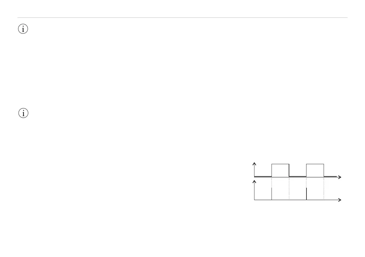
Edge triggering
The analog output is updated after a trigger edge. If the digital
output is selected only a single digital value, see Fig. 34, is
transmitted through the RS422 interface. Between the analog
output is temporarily stopped (“Sample and hold“), see Fig. 35.
U
I
D
0
t
t
Fig. 34 Rising trigger edge (above) and
digital output signal (below)
IMPORTANT!
Triggering is done
with an accordant
hardware only. Use
the optional available
triggerBOX1700 from
MICRO-EPSILON.
IMPORTANT!
The limit control is ac-
tivated only in the op-
eration mode „Trigger
switch mode“.