Page 36
Operation
optoNCDT 1700
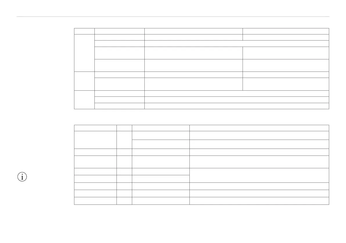
6.3 LED-Functions
LED Status Measurement mode Setup mode
state
illuminated Object is in the measurement range or error ...
off Sensor off or laser off
flashes slowly ...
Selected parameter value matches the
saved value
flashes quickly ...
Selected parameter value does not
match the saved value
output
speed
avg
illuminated or flashing Indication of the parameter value from level 1 Selected parameter value
flashing red Status „off“
zero
illuminated Sensor „master“ or „ set to mid-point“
off Normal operation
flashing Sensor as slave without synchronous signal
6.4 Inputs and Outputs
Signal Pin Explanation Configuration
Analog output 13
Current 4 ... 20 mA R
Limit
< (U
B
-6 V) / 20 mA; R
Limit
max. = 250 Ohm with U
B
= 11 V
Voltage 0 ... 10 VDC R
i
= 100 Ohm, I
max
= 5 mA, short-circuit protection from 7 mA,
2
Laser on/off 9 Switching input Laser operates if pin 9 is connected with GND
Zero 10 Switching input, Chap. 6.7
Connect 0.5 ... 3 s with GND: SET, connect 3 ... 6s with GND:
RESET
Switching output 1 8 Error or limit output 1
Open-Collector (NPN), I
max
= 100 mA, U
max
= 30 VDC,
Interrupt supply voltage to cancel the short-circuit protection
Switching output 2 7 Limit output 2
Sync +/Sync 3/4 Synchronizaton
1
Symmetrical synchron output (Master) or synchron input (Slave)
Tx +/Tx - 1/2 Serial output RS422 Terminate with 120 Ohm receive-site
Rx +/Rx - 12/11 Serial input RS422 Internally terminated with 120 Ohm
1) Input is used for triggering in trigger mode, see Chap. 6.14.
2) The use of a 10 nF capacitance at the entrance for interference suppression is recommended.
The LEDs on the
sensor, see Fig. 20,
have different indicator
functions depending
on whether the sensor
is in measurement
mode or setup mode.
IMPORTANT!
Disconnect or connect
the D-sub connection
between RS422 and
USB converter when
the sensor is discon-
nected from power
supply only.