Page 62
Serial Interface RS422
optoNCDT 1700
8.3 Set-up of the Commands
The commands for the sensors are comprised of command data which are transmitted in full duplex mode.
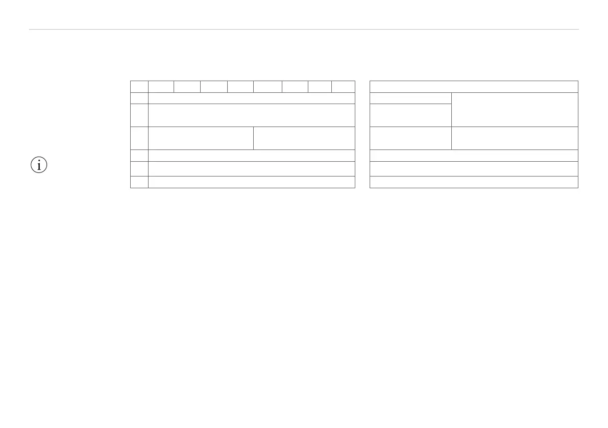
Each command packet is comprised of a whole number multiple of 32 bit words, see Fig. 44.
31 24 23 16 15 8 7 0 Contents
1 Header Start word
Command header
(2 words)
2 (ID)
Sensor identifier
e.g. „ILD1“
3
Command
(16 Bit)
Package length
(16 Bit)
Command code Data word quantity n+2
4 Data 1 1
st
Data word (4 Bytes)
5 ... ...
6 Data (n) n
th
Data word (4 Bytes)
Fig. 44 Structure of a command packet
Since most serial interfaces use an 8 bit data format, 4 consecutive bytes are combined into a 32 bit word.
Each command packet has a header consisting of two 32 bit words followed by the command and, if re-
quired, other data as well. The top two bits (No. 31 and 30) are always “0“ in the transmitted command.
Example:
Command SET_AVX. Sets the averaging number N for the moving and recursive average.
Command: 0x2075
Averaging number: N = 1024, therewith X = log2 1024 = 10 (= 0xA)
Data word: n = 1
Package length: 3
For further informations on this command, see Chap. 8.5.4.
IMPORTANT!
The sensor continues
to deliver measurement
values to the analog
output even while
communicating with
the sensor.


 To Next Page