Page 55
Operation
optoNCDT 1700
Edge triggering
The pulse interval t
i
between two trigger pulses must be at mini-
mum four cycles. Then the triggered measurement is issued
before a new trigger edge arrives. This results in a maximum
trigger frequency of 625 Hz for a measuring frequency of
2.5 kHz.
Level triggering
If the trigger level has changed, all measurements must be
issued before a new trigger lever can be identified. The sensor
requires a non-pulse period t
n
of 4 cycles. The minimum pulse
interval amounts therefore 5 cycles (t
i
= t
d
+ t
n
), see Fig. 39.
This results in a maximum trigger frequency of 500 Hz for a
measuring frequency of 2.5 kHz.
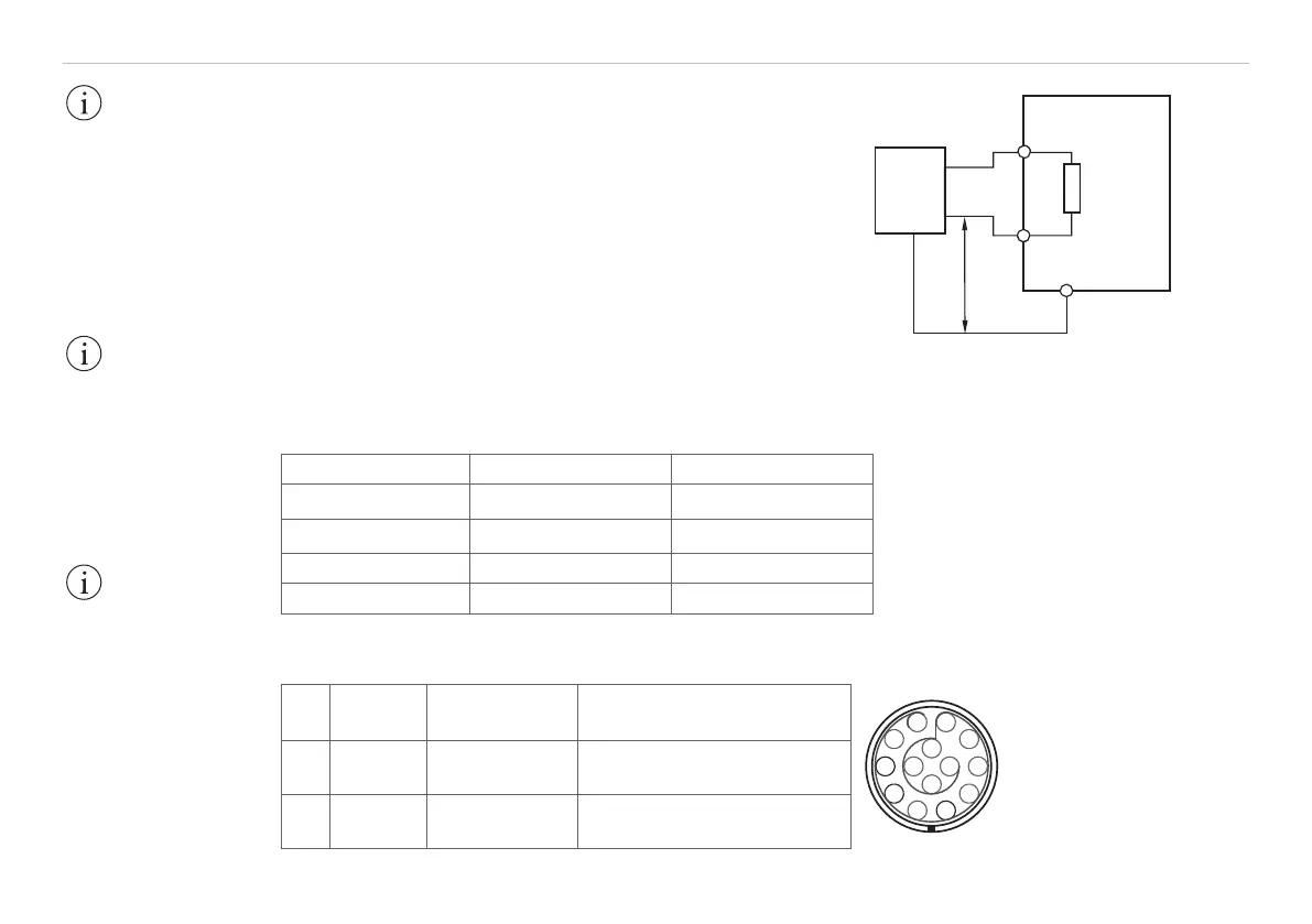
U
I
Trigger
source
optoNCDT1700
3
4
6
GND
Fig. 38 Trigger wiring
Trigger mode Edge triggering Level triggering
Pulse duration t
d
1 Cycle = 400 µs 1 Cycle = 400 µs
Non-pulse period t
n
3 Cycles = 1.2 ms 4 Cycles = 1.6 ms
Pulse interval t
I
4 Cycles = 1.6 ms 5 Cycles = 2.0 ms
Trigger frequency f
T
f
T
= f
M
/ 4 = 625 Hz f
T
= f
M
/ 5 = 500 Hz
Fig. 39 Minimum pulse values and maximum trigger frequency for speed = 1
6.14.5 Pin Assignment for External Trigger Signal
Pin Input Characteristics Color sensor cable PC1700-x
3
4
6
View on solder-pin side
male cable connector,
insulator
Fig. 40 Pin assignment
for external trigger signal
3
4
Trigger+
Trigger -
Differential
input
blue
pink
6 GND System ground black
IMPORTANT!
Exceeding the maxi-
mum trigger frequency
leads in measuring in-
accuracy shown by the
flashing zero LED and
the set error output (if
operation mode trigger/
error is selected).
IMPORTANT!
Triggering is done
with an accordant
hardware only. Use
the optional available
triggerBOX1700 from
MICRO-EPSILON.
IMPORTANT!
Connect the trigger
source ground with
the sensor ground
(GND, pin 6) before
sending trigger
signals.
f
M
= Measurement frequency