Page 79
Serial Interface RS422
optoNCDT 1700
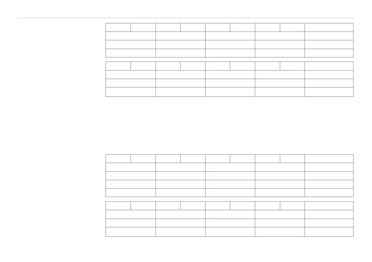
Format: 31 24 23 16 15 8 7 0 hex
„+“ „+“ „+“ 0x0d („CR“) 0x2B2B2B0D
„l“ „L“ „D“ „1“ 0x494C4431
0x20 0x84 0x00 0x02 0x20840002
Reply: 31 24 23 16 15 8 7 0 hex
„l“ „L“ „D“ „1“ 0x494C4431
0xA0 0x84 0x00 0x02 0xA0840002
0x20 0x20 0x0D 0x0A 0x20200D0A
8.5.9 Operation Mode
Name: SET_ERROROUTPUT
Description: Sets the use on synchron mode or trigger mode. Both modes exclude each other as the
input lines are used for synchronisation or triggering. Additionally the use of the switching outputs is set. In
error mode, switching output 1 is used as the error output. In switch mode, both outputs are used as limit
outputs.
Format: 31 24 23 16 15 8 7 0 hex
„+“ „+“ „+“ 0x0d („CR“) 0x2B2B2B0D
„l“ „L“ „D“ „1“ 0x494C4431
0x20 0x95 0x00 0x03 0x20950003
0x00 0x00 0x00 0x0X 0x0000000X
Reply: 31 24 23 16 15 8 7 0 hex
„l“ „L“ „D“ „1“ 0x494C4431
0xA0 0x95 0x00 0x02 0xA0950002
0x20 0x20 0x0D 0x0A 0x20200D0A
Standard setting:
Sync error
Options:
X = 0 > Snyc error
X = 1 > Snyc switch
X = 2 > Trigger error
X = 3 > Trigger switch