Page 54
Operation
optoNCDT 1700
Level Triggering
So long measurements are transmitted as the trigger condition
is fulfilled.
The GET_MEASVALUE command, see Chap. 8.5.19, supplies
the specified amount of digital measurements which must be
defined in the related parameter. Digital measurements are
output in binary, see Chap. 8.2.1 or ASCII format, see Chap.
8.2.2, in trigger mode.
6.14.3 Trigger Signal Levels
The inputs (Trig+, Trig-;, see Fig. 40) are used for external
triggering. The necessary signal levels comply to the LVDS
(Low Voltage Differential Signals) specification. Thus only LVDS
driver circuits with 3.3 V operation voltage are used for trigger-
ing.
The difference between both input signals Trig+ (pin 3) and
Trig- (pin 4) must be according to amount greater than 100
mV. Each individual signal may lie in the range between 0 V
and +2.9 V related to GND. The sensor detects a high level,
see Fig. 37, if the voltage on Trig+ is greater than on Trig-. The
optoNCDT1700 contains a terminating resistor, see Fig. 38,
between pin 3 and 4 for line matching.
6.14.4 Trigger Pulse
The trigger pulse duration td must be one cycle time (= 1 /
measuring frequency) at least. Shorter measuring frequencies
need a longer trigger pulse duration
(e.g. from t
d
= 400 μs with speed = 1 up to t
d
= 3.2 ms with
speed = 1/8).
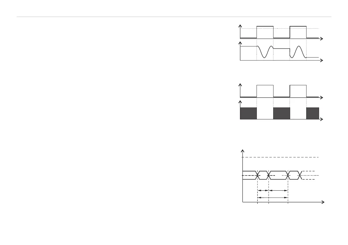
U
I
D
0
t
t
Fig. 35 High trigger level (above) and
analog output signal (below)
U
I
D
0
t
t
Fig. 36 Low trigger level (above) and
digital output signal (below)
U
I
2.9 V
Trig -
Trig+
t
H L H
t
d
t
n
t
i
Fig. 37 Timing trigger signal
t
d
Pulse duration
t
n
Non-pulse period
t
i
Pulse interval
U
I
Input signal level