Page 109
Appendix| Pin Assignment RS422 Connection
optoNCDT 1700
A 5 Pin Assignment RS422 Connection
X = Cable length in m
PC1700-X ILD1700
S4 OFF
S3 OFF
S2 ON
S1 ON
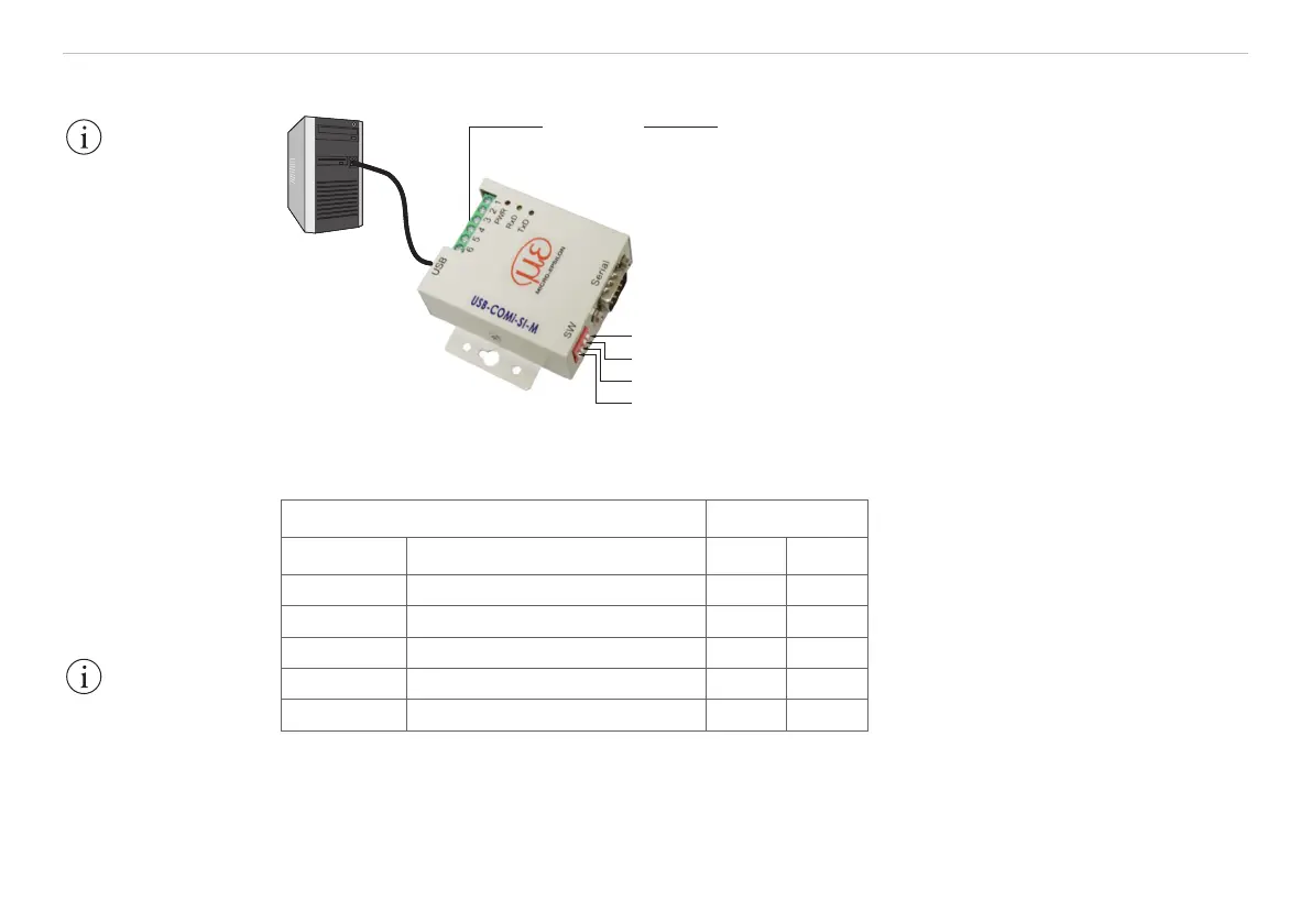
Fig. 56 Principle setup
Cross the lines for connections between sensor and PC.
ILD1700 Converter
Signal Color PC1700 Signal Pin
RX- yellow TX- 1
RX+ gray TX+ 2
TX+ green RX+ 3
TX- brown RX- 4
GND (Pin 6) black ground 5
Fig. 57 Pin assignment and wiring
IMPORTANT!
The system ground
must be connected
with the terminal
ground (USB converter,
pin 5) before
connecting the Rx and
Tx lines.
IMPORTANT!
Disconnect or connect
the D-sub connection
between RS422 and
USB converter when
the sensor is discon-
nected from power
supply only.